Maintenance
ESIE11-02
5–4
3
1
55
1.2
Maintenance of the Main Parts
Preventive
maintenance
A program of scheduled maintenance should be set up and followed. The items mentioned are to be
used as a guide and must be used in combination with sound electrical and refrigeration workmanship
to ensure trouble free operation and performance.
Unit Casing
Follow the below instructions to check the unit casing.
Compressor
Follow the instructions below to check the compressor:
■
Check crankcase heater operation. Switch of the compressor and carefully touch the crankcase
heater area by hand.
No operation can cause compressor damage when the ambient temperature reaches a low
temperature.
Evaporator and
condenser
Follow the instructions below to check the evaporator and condenser:
■
Inspect the evaporator tubes or condenser plates after the first operating season. This condition
indicates the required frequency of cleaning and also whether water treatment is needed in the
chilled water circuit.
■
Check the air plugs and drain plugs to prevent or detect water leakage.
■
Check pressure-drop and water flow.
■
Record temperature difference between in / out and water out/ refrigerant temperature.
■
Inspect evaporator insulation. If damaged, repair to avoid water between insulation and evaporator
shell.
■
Inspect water and refrigerant connections.
■
If the evaporator heater-tape is installed, check operation by direct power connection and
hand-touch.
■
brush cleaning. Abnormal high condensing-pressures are an indication for periodic cleaning.
Unit switchbox
Follow the instructions below to check the unit switchbox:
■
Check all power connections for tightness.
■
Check compressor motor terminals.
■
Inspect wiring for any signs of overheating (discolouring).
■
Remove all dust and debris from the switchbox. Replaced coils and components should not be left
in the unit control panel.
■
Check all field-wired terminals.
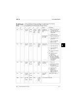
Check if...
If not, then...
The paint of the unit casing is
intact.
Touch-up with paint.
All plate work is screwed down in
position.
Screw the plate work down in position.
Содержание EUWY 24KBZW1 Series
Страница 2: ......
Страница 8: ...ESIE11 02 vi Table of Contents 3 1 4 5...
Страница 10: ...Introduction ESIE11 02 viii 3 1 4 5...
Страница 12: ...ESIE11 02 1 2 Part 1 System Outline 3 1 1 5...
Страница 86: ...Wiring Layout ESIE11 02 1 76 Part 1 System Outline...
Страница 88: ...ESIE11 02 2 2 Part 2 Functional Description 3 1 2 5...
Страница 128: ...The Digital Controller ESIE11 02 2 42 Part 2 Functional Description 3 1 2 4 5...
Страница 130: ...ESIE11 02 3 2 Part 3 Troubleshooting 3 1 3 5...
Страница 168: ...ESIE11 02 4 2 Part 4 Commissioning and Test Run 3 1 4 5...
Страница 198: ...Test Run and Operation Data ESIE11 02 4 32 Part 4 Commissioning and Test Run 3 1 4 5...
Страница 200: ...ESIE11 02 5 2 Part 5 Maintenance 3 1 5...
Страница 210: ...ESIE11 02 4 Index 3 1 4 5...


