D
–EIMAC00708-16EN - 55/76
Compressor
The single-screw compressor is of the semi-hermetic type with asynchronous three-phase two-pole engine which is
directly splined to the main shaft. The intake gas from the evaporator cools the electrical engine before entering the
intake ports. Inside the electrical engine, there are temperature sensors completely covered by the coil winding that
constantly monitor engine temperature. Should the coil winding temperature become very high (120°C), a special
external apparatus that is connected to the sensors and to the electronic controller will de -activate the corresponding
compressor.
The compressors of EW AD100E÷210E-SS/SL, ERAD120E÷250E-SS, ERAD120E÷240E-SL units are Fr3100 and the
compressors of EW AD260E÷410E-SS, EW AD250E÷400E-SL and ERAD310E÷490E-SS, ERAD300E÷460E-SL units are
F3. Fr3100 compressor has one single satellite on the upper section of the main screw; F3 compressors have two
satellites symmetrically positioned on the main screw sides.
There are only two moving rotating parts in Fr3100 compressor and three moving parts in F3 compressors and th ere are
no other parts in the compressor with an eccentric and/or alternative movement.
The basic components are therefore only the main rotor and the satellites that carry out the compression process,
meshing perfectly together.
Compression sealing is done thanks to a suitably shaped special composite material that is interposed between the main
screw and the satellite. The main shaft on which the main rotor is splined is supported by 2 ball bearings. The system
made up in this way is both statically and dynamically balanced before assembly.
Figure 27 - Picture of Fr3100 compressor
Figure 28 - Picture of F3 compressor
On the upper part of Fr3100 compressor, there is a large access cover allowing quick and easy maintenance; on F 3
compressor, the access to the internal parts is allowed by two covers positioned sidewise.
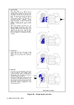
Compression process
With the single-screw compressor the intake, compression and discharge process takes place in a continuous manner
thanks to the satellite. In this process the intake gas penetrates into the profile between the rotor, the teeth of the satel lite
and the compressor body. The volume is gradually reduced by compression of the refrigerant. The compressed gas
under high pressure is thus discharged in the built-in oil separator. In the oil separator the gas/ oil mixture and the oil are
collected in a cavity in the lower part of the compressor, where they are injected into the compression mechanisms in
order to ensure the compression’s sealing and lubrification of the ball bearings.
Содержание ERAD 120E-SL
Страница 43: ...D EIMAC00708 16EN 43 76 Figure 18 Field Wiring Diagram...
Страница 75: ...D EIMAC00708 16EN 75 76...


