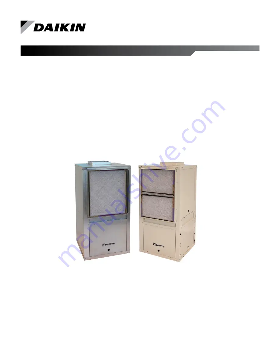
Daikin Enfinity VFC Скачать руководство пользователя страница 1

Installation and Maintenance Manual  IM 930-6

Group: 

WSHP

Part Number: 

910157591

Date: 

September 2014

Enfinity™ Vertical Water Source Heat Pumps

Model VFC Standard Range & VFW Geothermal
Unit Sizes 009 – 070 / R-410A Refrigerant

People and ideas you can trust.

Содержание Enfinity VFC

Страница 1: ...nance Manual IM 930 6 Group WSHP Part Number 910157591 Date September 2014 Enfinity Vertical Water Source Heat Pumps Model VFC Standard Range VFW Geothermal Unit Sizes 009 070 R 410A Refrigerant People and ideas you can trust ...

Страница 2: ......

Страница 3: ...dule 208 230 460 60 Hz 3 Phase 26 MicroTech III Unit Controller with Optional ECM Motor Desuperheater and I O Expansion Module 208 230 460 60 3 Phase 27 MicroTech III Unit Controller with PSC Motor Desuperheater and I O Expansion Module for Hot Gas Reheat Control Unit Sizes 019 070 208 230 60 1 Phase 28 Thermostat Connections 29 7 Day Programmable Electronic Thermostat P N 668375301 29 Non Program...

Страница 4: ...truction Type 12 18 B Standard w 2 Filter Rack C Standard w Compressor Sound Blanket D Standard w Compressor Sound Blanket and 2 Filter Rack F Indoor Air Quality IAQ w 2 Filter Rack G Indoor Air Quality IAQ w Compressor Sound Blanket H Indoor Air Quality IAQ w Compressor Sound Blanket and 2 Filter Rack Heating Options 14 20 A 5 0 kW Electric Heat B 10 0 kW Electric Heat Dehumidification 15 21 22 A...

Страница 5: ...cked The contents may be damaged in transit due to rough handling even though the carton may not show external damages When the damage is discovered upon unpacking make a written request for inspection by the carrier s agent within fifteen 15 days of the delivery date and file a claim with the carrier Pre Installation WARNING The installer must determine and follow all applicable codes and regulat...

Страница 6: ... Unit must be located on top of a vibration absorbing material such as a rubber Isolation pad that is the same size as the base of the unit to minimize vibration and noise See Figure 9 on page 10 Minimum distance requirement from return air duct collar to wall for non ducted units Model Distance 009 012 5 inches 015 024 5 inches 030 036 6 inches 042 048 8 inches 060 070 10 inches Figure 1 Typical ...

Страница 7: ...ition piece down to the size of the discharge collar on the unit With metal duct material the sides of the elbow and entire branch duct should be internally lined with acoustic insulation for sound attenuation Glass fiber duct board material is more absorbing and may permit omission of the flexible connector The ductwork should be laid out so that there is no line of sight between the unit dischar...

Страница 8: ... and blow down making sure city water fill valves are set to make up water at the same rate Check the pressure gauge at pump suction and manually adjust the makeup to hold the same positive steady pressure both before and after opening the drain valves Flush should continue for at least two hours or longer until the drain water is clean and clear Units must be checked for water leaks upon initial ...

Страница 9: ...10 F 43 C 90 F 32 C Minimum GPM Ton 1 5 Nominal GPM Ton 3 0 Maximum GPM Ton 4 0 Notes 1 Maximum and minimum values may not be combined If one value is at maximum or minimum the other two conditions may not exceed the normal condition for standard units Extended range units may combine any two maximum conditions but not more than two with all other conditions being normal conditions 2 This is not a...

Страница 10: ...tical Unit Piping 4 Some flexible hose threaded fittings are supplied with sealant compound If not apply Teflon tape for a tight seal 5 Supply and return shutoff valves are required at each unit The return valve is used for balancing and should have a memory stop so that it can always be closed off but can only be reopened to the proper position for the flow required 6 Do not connect any unit to t...

Страница 11: ...ower and that shown on the unit data plate Line and low voltage wiring must comply with local codes or the National Electrical Code whichever applies 2 Apply correct line voltage to the unit A 7 8 22mm hole A disconnect switch near the unit is required by code Power to the unit must be sized correctly and have dual element Class RK5 fuses or an HACR circuit breaker for branch circuit overcurrent p...

Страница 12: ...output is on sending a signal to the LED when the A terminal is configured by JP4 being open Remote Reset of Automatic Lockouts The Remote Reset feature provides the means to remotely reset some lockouts generated by high pressure and or low temperature faults When the MicroTech III unit controller is locked out due to one of these faults and the cause of the fault condition has been cleared energ...

Страница 13: ...Room Sensor DC Signal Common TB2 1 R 24 VAC TB2 2 A Alarm Output TB2 3 W2 Thermostat Heat Stage 2 Input TB2 4 W1 Thermostat Heat Stage 1 Input TB2 5 Y2 Thermostat Cool Stage 2 Input TB2 6 Y1 Thermostat Cool Stage 1 Input TB2 7 G Thermostat Fan Input TB2 8 O Thermostat Tenant Override Input TB2 9 C 24 VAC Common TB3 1 E Emergency Shutdown Input TB3 2 U Unoccupied Occupied Input L1 1 L1 1 Line Volta...

Страница 14: ...ail Fault Flash Flash ON Low Suction Temp LT1 Fault Flash OFF OFF Room Temp Sensor Fail with Room Sensor Control Only Fault Flash Flash ON Condensate Overflow Cooling Dehumidification Modes Only Fault ON OFF OFF Low Entering Water Temp Heating Compressor Inhibit No Display with Boilerless EH Fault Flash OFF Flash Serial EEPROM Corrupted Fault ON ON ON Service Test Mode Enabled Mode Flash Flash Fla...

Страница 15: ...nd 360 seconds is generated at power up Figure 11 MicroTech III Unit Controller Terminal Locations Figure 12 Location of Configuration Jumpers on the MicroTech III Unit Controller www DaikinApplied com 15 Enfinity Vertical Water Source Heat Pumps IM 930 6 ...

Страница 16: ...Expansion Module will be the standard control system for two stage Water Source Heat Pump equipment i e large vertical units The I O Expansion Module has outputs to control electric heat on a standard Water Source Heat Pump The I O Expansion Module has outputs for multi speed fans on a standard Water Source Heat Pump The I O Expansion Module has an independent LED annunciator to identify operation...

Страница 17: ...n ECM motor JP6 Open JP5 Open Three Speed Fan JP6 Shorted Not Used JP7 JP7 Open Lead Compressor Option JP8 JP8 Open Compressor 1 is Lead factory default setting JP8 Shorted Compressor 2 is Lead Valid for Dual Compressor Models Only Available with secondary heating options in addition to ECM motor Table 12 I O Expansion Module LED Fault Outputs Description Type Yellow Green Red Invalid Jumper Confi...

Страница 18: ...ant override The user has the capability of substituting the wall sensor with a duct mounted return air sensor Each unit controller orchestrates the following unit operations Enable heating and cooling to maintain setpoint based on a room sensor Enable fan and compressor operation Monitor all equipment protection controls Monitor discharge air temperature Monitor leaving water temperature Relay st...

Страница 19: ...nable the MS TP MAC address to be set in the range 0 127 Four green status LEDs on the communication module indicate communication activity on the MS TP communication network and with the unit controller Figure 15 MicroTech III BACnet Water Source Heat Pump Snap in Communication Module MicroTech III Unit Controller with BACnet MS TP Communication Module orchestrates the following unit operations E...

Страница 20: ...Controls Figure 16 LonWorks Communication Module Placement on MicroTech III Unit Controller IM 930 6 Enfinity Vertical Water Source Heat Pumps 20 www DaikinApplied com ...

Страница 21: ...igh Notes n a Not Available Not available at time of publication Unit Size 009 through 015 115 60 1 208 230 60 1 and 265 60 1 To change between high and low speed interchange the red and black wires Figure 17 Sizes 009 through 015 115 60 10 208 230 60 1 265 60 1 Unit Size 019 through 036 208 230 60 1 and 265 60 1 Fan motors on unit sizes 019 036 in both 208 230 60 1 and 265 60 1 voltages Figure 18...

Страница 22: ...r position terminal block In order to change between high and low speed interchange the wires on the black and red terminals Figure 23 Sizes 024 036 208 230 3 Notes All motors have a wiring label that is keyed for proper wiring operation Check unit wiring dia gram on electrical access panel for proper unit operation Not all labels are the same Units leaving the factory are wired for high or low fa...

Страница 23: ...mpressor s against short cycling After a few minutes of operation check the discharge grilles for cool air delivery Measure the temperature difference between entering and leaving water It should be approximately 1 1 2 times greater than the heating mode temperature difference For example if the cooling temperature difference is 15 F 8 C the heating temperature difference should be 10 F 5 C Withou...

Страница 24: ...mperature LWT sensor is factory installed Legend Item Description C1 Capacitor Compressor C2 Capacitor Fan CC Compressor Contactor CM Compressor Motor CDS Condensate Overflow Sensor DAT Discharge Air Temp Sensor HP High Pressure Switch HTR Electric Heater Cartridge IOEXP I O Expansion Board Harness ISO NC Isolation Valve Normally Closed ISO NO Isolation Valve Normally Open LED1 LED Annunciator Har...

Страница 25: ...ic Heat Legend Item Description C1 Capacitor Compressor C2 Capacitor Fan CC Compressor Contactor CM Compressor Motor CDS Condensate Overflow Sensor DAT Discharge Air Temp Sensor EWT Entering Water Temp Sensor HP High Pressure Switch HTR Electric Heater Cartridge IOEXP I O Expansion Board Harness ISO NC Isolation Valve Normally Closed ISO NO Isolation Valve Normally Open LED1 LED Annunciator Harnes...

Страница 26: ...ctric Heat Legend Item Description C1 Capacitor Compressor C2 Capacitor Fan CC Compressor Contactor CM Compressor Motor CDS Condensate Overflow Sensor DAT Discharge Air Temp Sensor EWT Entering Water Temp Sensor HP High Pressure Switch HTR Electric Heater Cartridge IOEXP I O Expansion Board Harness ISO NC Isolation Valve Normally Closed ISO NO Isolation Valve Normally Open LED1 LED Annunciator Har...

Страница 27: ...D Legend Item Description C1 Capacitor Compressor C2 Capacitor Fan CC Compressor Contactor CM Compressor Motor CDS Condensate Overflow Sensor DAT Discharge Air Temp Sensor EWT Entering Water Temp Sensor HP High Pressure Switch HTR Electric Heater Cartridge IOEXP I O Expansion Board Harness ISO NC Isolation Valve Normally Closed ISO NO Isolation Valve Normally Open LED1 LED Annunciator Harness LED2...

Страница 28: ...wire to be capped Legend Item Description C1 Capacitor Compressor C2 Capacitor Fan CC Compressor Contactor CM Compressor Motor COS Condensate Overflow Sensor DAT Discharge Air Temp Sensor EWT Entering Water Temp Sensor HP High Pressure Switch HTR Electric Heater Cartridge IOEXP I O Expansion Board Harness ISO NC Isolation Valve Normally Closed ISO NO Isolation Valve Normally Open DSHP Desuperheate...

Страница 29: ...thermostat 668375401 When remote reset of a lockout condition is re quired at the wall thermostat it will be necessary to utilize a conductor between terminal O on the wall thermostat to terminal O on the MicroTech III unit controller non programmable stat only Optional Remote Sensor P N 66720401 1 Remove cover from remote sensor housing 2 Select an appropriate location for mounting the remote sen...

Страница 30: ...ll Mounted Room Temperature Sensors For installation instructions refer to IM 955 Figure 26 MicroTech III Wall Sensor Details Fan Control Slide Switch Mode Control Slide Switch Status LED Green 0 to 1 5 K ohm Potentiometer Tenant Override Momentary Push Button Switch 4 59 3 75 Specifications Thermistor resistance 10kΩ Conforms to advance thermal products curve 2 Ambient Temperature Limits Shipping...

Страница 31: ... multiple unit control board is an accessory used when up to 3 units are controlled from a single thermostat Typically the control panel and board is centrally mounted between the units and thermostat A maximum of 2 boards may be used together if up to 6 units must be connected and controlled from a single thermostat For detailed installation instructions refer to IM 952 This version of the contro...

Страница 32: ...he guidelines below For piping length up to 15 feet Use 3 8 O D or larger copper tube For piping lengths of 15 feet to 60 feet Use 1 2 O D copper tube Notes All exposed water lines must be insulated with 3 8 wall closed cell insulation Install shut off valves on desuperheater supply and return lines 11 Refill tank by opening the water tank supply valve 12 Vent air from the system by opening a hot ...

Страница 33: ...air tempera tures the values printed below are to be taken as suggested pressure and temperatures All Daikin water source heat pumps are designed for commercial use The units are designed for the cooling mode of operation and fail safe to cooling The reversing valve is energized for the heating mode of operation Superheat Head Pressure Water Delta T 8 to 14 degrees 335 355 PSIG 10 to 14 All inform...

Страница 34: ...re Fault OFF OFF ON Loose wire connection on low pressure circuit Failed low pressure switch Unit is low on charge Table 17 Compressor Low Suction Temp Description Type Yellow Green Red Compressor Low Suction Temp Fault Flash Flash ON Check water flow heating operation Check airflow cooling operation Entering water and air temperatures should be within the operating limits Table 18 Condensate Over...

Страница 35: ...ow Low Low Low Pressure Overcharge System High High High Normal High Normal Normal High Pressure Low Low Air Flow Heating High High High High Low High Low High Pressure Normal Low Air Flow Cooling Low Low Low Low High High Low Low Temp Normal Low Water Flow Heating Low Low Low Low High Low High Low Temp Normal Normal Low Water Flow Cooling High High High High Low Low High High Pressure High Air Fl...

Страница 36: ...compressor capacitor Insufficient cooling or heating Check for lock rotor amp draw Check for defective compressor internal windings with ohm meter Check for proper air flow filter could be dirty Check for low refrigerant charge Check amp draw on blower assembly Fan operates compressor does not Compressor runs in short cycle Neither fan nor compressor runs and all LED lights are off Check capacitor...

Страница 37: ...lve and back to the suction side of the compressor to complete the cycle Figure 36 Heating Mode Return Air Thermal Expansion Valve Coaxial Heat Exchanger Reversing Valve Conditioned Air Heating Blower Water In Water Out Sensing Bulb and Capillary Tube Compressor Coil Air to Refrigerant Heat Exchanger Heating Refrigeration Cycle When the wall thermostat is calling for HEATING the reversing valve di...

Страница 38: ... s control or thermostat inputs However only one drive terminal R or C can be connected to any individual input terminal or damage may result Some control inputs are not accessible to the end user for example HP LP SLTS and COF Typically the Microtech III unit controller s R 24VAC terminal is used to drive the board s thermostat inputs and control inputs by connecting it to the R terminal of an in...

Страница 39: ..._______________________________________ Loop System Free of Air ____________________________________________________________________ Filters Clean _ ____________________________________________________________________________ Condensate Traps Installed _ _________________________________________________________________ Note No answers below require notice to installer by memorandum attached copy O...

Страница 40: ...e The difference between the two is referred to as P P can be converted to GPM by looking in the equipment specificaton catalog Caution P GPM Note A conversion table must be used to find GPM from Delta P measurements Loop Fluid Temperature Rise Drop through Coaxial Heat Exchanger EWT LWT T EWT F Out__________________ minus LWT F Out___________________ equals Fluid T_ _______________ T is the rise ...

Страница 41: ...ts indicated for each unit per installation on previous page Model Serial H P EWT 3 LWT 4 EWP 1 LWP 2 EAT 5 LAT 6 Volts Amps Cool ing Check Air Filter and Coil Comments more comments on next sheet 1 2 3 4 5 6 7 8 9 10 11 12 13 14 15 16 17 18 19 20 21 22 23 24 25 26 27 28 29 30 31 32 33 34 35 36 37 38 39 40 41 42 Part No ______________________________ ...

Страница 42: ...IM 930 6 Enfinity Vertical Water Source Heat Pumps 42 www DaikinApplied com Notes Comments Form WS CTS 00 01 Rev 4 14 ...

Страница 43: ...www DaikinApplied com 43 Enfinity Vertical Water Source Heat Pumps IM 930 6 This page left blank intentionally ...

Страница 44: ...andard terms and conditions of sale including Limited Product Warranty Consult your local Daikin Applied representative for warranty details Refer to Form 933 430285Y To find your local Daikin Applied representative go to www DaikinApplied com Aftermarket Services To find your local parts office visit www DaikinApplied com or call 800 37PARTS 800 377 2787 To find your local service office visit ww...

Отзывы: