background image

6 Electrical installation

Installation manual

20

EL23E

Daikin Altherma 3 R MT F

4P708476-1 – 2023.03

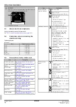
Connect X11Y to X11YB.

A

10

9

S1S

N

L

5

6

1N~, 50 Hz, 

230 V AC, 6.3 A

1 2 3

a

b

c

B

A

B

5 6

1 2 3

X2M

X5M

9 10

X11YA

X11YB

X11Y

X1A

X1M

a

b

c

a

Interconnection cable (=main power supply)

b

Normal kWh rate power supply

c

Preferential power supply contact

3

Fix the cables with cable ties to the cable tie mountings.

INFORMATION

In  case  of  preferential  kWh  rate  power  supply,  connect
X11Y  to  X11YB.  The  necessity  of  separate  normal  kWh
rate  power  supply  to  indoor  unit  (b)  X2M/5+6  depends  on
the type of preferential kWh rate power supply.

Separate connection to the indoor unit is required:

▪ if  preferential  kWh  rate  power  supply  is  interrupted

when active, OR

▪ if no power consumption of the indoor unit is allowed at

the preferential kWh rate power supply when active.

6.3.2

To connect the backup heater power
supply

Backup heater

type

Power supply

Wires

*6V

1N~ 230 V (6V3)

2+GND

3~ 230 V (6T1)

3+GND

*9W

3N~ 400 V

4+GND

[9.3] 

Backup heater

WARNING

The backup heater MUST have a dedicated power supply
and MUST be protected by the safety devices required by
the applicable legislation.

CAUTION

To  guarantee  the  unit  is  completely  earthed,  ALWAYS
connect  the  backup  heater  power  supply  and  the  earth
cable.

The backup heater capacity can vary, depending on the indoor unit
model.  Make  sure  that  the  power  supply  is  in  accordance  with  the
backup heater capacity, as listed in the table below.

Backup

heater type

Backup

heater

capacity

Power

supply

Maximum

running

current

Z

max

*6V

2 kW

1N~ 230 V

(a)

9 A

4 kW

1N~ 230 V

(a)

17 A

(b)(c)

0.22 Ω

6 kW

1N~ 230 V

(a)

26 A

(b)(c)

0.22 Ω

2 kW

3~ 230 V

(d)

5 A

4 kW

3~ 230 V

(d)

10 A

6 kW

3~ 230 V

(d)

15 A

*9W

3 kW

3N~ 400 V

4 A

6 kW

3N~ 400 V

9 A

9 kW

3N~ 400 V

13 A

(a)

6V3

(b)

Electrical equipment complying with EN/IEC 61000-3-12
(European/International Technical Standard setting the limits for
harmonic currents produced by equipment connected to public
low-voltage systems with input current >16 A and ≤75 A per
phase).

(c)

This equipment complies with EN/IEC 61000‑3‑11 (European/
International Technical Standard setting the limits for voltage
changes, voltage fluctuations and flicker in public low-voltage
supply systems for equipment with rated current ≤75 A) provided
that the system impedance Z

sys

 is less than or equal to Z

max

 at the

interface point between the user's supply and the public system. It
is the responsibility of the installer or user of the equipment to
ensure, by consultation with the distribution network operator if
necessary, that the equipment is connected only to a supply with
a system impedance Z

sys

 less than or equal to Z

max

.

(d)

6T1

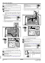
Connect the backup heater power supply as follows:

X6M

F1B

Q1DI

a

b

a

Factory-mounted cable connected to the contactor of the
backup heater, inside the switch box (K5M)

b

Field wiring (see table below)

Содержание ELVZ-E9W

Страница 1: ...llation manual Daikin Altherma 3 R MT F English Installation manual Daikin Altherma 3 R MT F ELVZ12S18E 6V ELVZ12S23E 6V ELVZ12S18E 9W ELVZ12S23E 9W 1 2 3 9 A B C Z 1 2 3 9 https daikintechnicaldatahu...

Страница 2: ...5 After connecting the electrical wiring to the indoor unit 27 7 Configuration 27 7 1 Overview Configuration 27 7 1 1 To access the most used commands 28 7 2 Configuration wizard 28 7 2 1 Configuratio...

Страница 3: ...nit installation 45 WARNING Installation shall be done by an installer the choice of materials and installation shall comply with the applicable legislation In Europe EN378 is the applicable standard...

Страница 4: ...iring does NOT touch the refrigerant gas pipe which can be very hot a a Refrigerant gas pipe WARNING The backup heater MUST have a dedicated power supply and MUST be protected by the safety devices re...

Страница 5: ...oroughly 4 1 1 Installation site requirements of the indoor unit The indoor unit is designed for indoor installation only and for the following ambient temperatures Space heating operation 5 30 C Spac...

Страница 6: ...d by persons 1 2 3 4 PATTERN 1 PATTERN 2 PATTERN 3 PATTERN 4 a b a b H release H release 1a b A 1b H release H release 2a b c2 c1 A B 2b A b 3a c2 c1 A Ventilation openings N A Between room A and B N...

Страница 7: ...he minimum floor area if you provide 2 openings one at the bottom one at the top between the room and the outside to ensure natural ventilation The room must be protected from frost WARNING Chimney co...

Страница 8: ...penings must comply with the following conditions Bottom opening Anv Must be a permanent opening that cannot be closed Must be completely located between 0 and 300 mm from the floor Must be Anv min mi...

Страница 9: ...Anv min and with the Conditions ventilation openings on previous page See table 3 For H1 Can the maximum chimney length be respected and is the chimney practically feasible See table 2 Do you need a...

Страница 10: ...2 m 10 52 m 3 65 kg 14 80 m 11 77 m 3 85 kg 16 46 m 13 10 m 4 05 kg 18 22 m 14 50 m Table 2 Minimum release height Take the following into account For intermediate floor areas use the column with the...

Страница 11: ...kg For intermediate floor areas use the column with the lower value Example If the floor area is 7 25 m use the column of 6 00 m For intermediate release height values use the row with the lower valu...

Страница 12: ...he height of the opening must be 20 mm a2 Top opening for natural ventilation between room A and the outside Must be a permanent opening that cannot be closed Must be 50 of Anv min minimum bottom open...

Страница 13: ...of the unit 2 Tilt the switch box to the front and lift it out of its hinges 1 2 2 T25 3 Place the switch box lower on the unit Use the 2 hinges located lower on the unit 3 3 4 2 3 To close the indoo...

Страница 14: ...is document are NOT applicable 5 1 Preparing refrigerant piping 5 1 1 Refrigerant piping requirements Also see 4 1 2 Special requirements for R32 units 4 5 for additional requirements Piping length Se...

Страница 15: ...operate is 1 bar 0 1 MPa Water pressure Space heating cooling circuit The maximum water pressure is 3 bar 0 3 MPa Provide adequate safeguards in the water circuit to ensure that the maximum pressure...

Страница 16: ...recommended e Pressure relief valve max 10 bar 1 0 MPa mandatory f Tundish mandatory g Expansion vessel recommended NOTICE It is recommended to install shut off valves to domestic cold water in and d...

Страница 17: ...ake sure you comply with the applicable legislation NOTICE Pump To prevent blocking of the pump rotor commission the unit as quickly as possible after filling the water circuit INFORMATION Make sure b...

Страница 18: ...al inputs 423 Safety thermostat See 6 3 9 To connect the safety thermostat normally closed contact 424 Smart Grid See 6 3 10 To connect a Smart Grid 425 WLAN cartridge See 6 3 11 To connect the WLAN c...

Страница 19: ...stallation manual of the wired room thermostat digital or analogue multi zoning base unit Addendum book for optional equipment In this case You need to connect the wired room thermostat digital or ana...

Страница 20: ...ary depending on the indoor unit model Make sure that the power supply is in accordance with the backup heater capacity as listed in the table below Backup heater type Backup heater capacity Power sup...

Страница 21: ...eaker field supply SWB Switch box X6M Terminal field supply NOTICE Do NOT cut or remove the backup heater power supply cable 6 3 3 To connect the shut off valve INFORMATION Shut off valve usage exampl...

Страница 22: ...le tie mountings 6 3 5 To connect the domestic hot water pump Wires 2 GND 0 75 mm DHW pump output Maximum load 2 A inrush 230 V AC 1 A continuous 9 2 2 DHW pump 9 2 3 DHW pump schedule 1 Open the foll...

Страница 23: ...own in the illustration below 7 9 YC Y2 X2M 1 2 3 A4P 1 2 Wires connected to the space cooling heating ON OFF output 3 Wire between X2M and A4P A4P Installation of EKRP1HBAA is required A Y2 7 B A B 7...

Страница 24: ...ble tie mountings INFORMATION Installation of a safety thermostat field supply is required for the main zone otherwise the unit will NOT operate NOTICE A safety thermostat MUST be installed on the mai...

Страница 25: ...Grid contacts can activate the following Smart Grid modes Smart Grid contact Smart Grid operation mode 1 2 0 0 Free running 0 1 Forced off 1 0 Recommended on 1 1 Forced on The use of a Smart Grid pul...

Страница 26: ...ow voltage connections STEP 3 High voltage connections 1 High voltage Smart Grid contact 1 2 High voltage Smart Grid contact 2 a b Coil sides of relays c d Contact sides of relays e Jumper factory mou...

Страница 27: ...f you do NOT configure the system correctly it might NOT work as expected The configuration influences the following The calculations of the software What you can see on and do with the user interface...

Страница 28: ...Turn the left dial to select the first part of the setting and confirm by pressing the dial 00 01 02 03 04 05 06 07 08 09 0A 0B 0C 0D 0E 0 1 2 3 4 Turn the left dial to select the second part of the s...

Страница 29: ...ic hot water heating and space heating stops To manually recover it via the user interface go to the Malfunctioning main menu screen and confirm whether the backup heater can take over the heat load o...

Страница 30: ...r a backup heater with 2 steps If 2 steps the capacity of the second step depends on this setting It can also be chosen to have a higher capacity of the second step in emergency Code Description 9 3 3...

Страница 31: ...r ambient temperature for cooling In Weather dependent mode the desired leaving water temperature depends on the outdoor ambient temperature Code Description 2 4 N A Setpoint mode Fixed WD heating fix...

Страница 32: ...0E C Eco setpoint The storage economic temperature denotes the lower desired tank temperature It is the desired temperature when a storage economic action is scheduled preferably during day Code Descr...

Страница 33: ...ceed 7 3 3 Slope offset curve Slope and offset Define the weather dependent curve by its slope and offset Change the slope to differently increase or decrease the temperature of the leaving water for...

Страница 34: ...nly available to installers To change the weather dependent curve Zone Go to Main zone Heating 2 5 Main zone Heating WD curve Main zone Cooling 2 6 Main zone Cooling WD curve Additional zone Heating 3...

Страница 35: ...ble if C 2 Space heating cooling On Code Description 2 A C 05 External room thermostat type for the main zone 1 1 contact The used external room thermostat can only send a thermo ON OFF condition Ther...

Страница 36: ...efit kWh power supply Smart grid operation mode Allow electrical heaters Limit setting kW Enable room buffering Allow heater Allow pump 9 Installer settings Configuration wizard Domestic hot water Bac...

Страница 37: ...guide The indoor unit is properly mounted The outdoor unit is properly mounted The following field wiring has been carried out according to this document and the applicable legislation Between the lo...

Страница 38: ...manually 1 Go to Stop air purge 2 Select OK to confirm INFORMATION When air purging in automatic mode the first air purge is always for the main zone the second started air purge is always for the ad...

Страница 39: ...t programming screen 4 Select OK to confirm Result The underfloor heating screed dryout starts It stops automatically when done To stop the test run manually 1 Go to Stop UFH screed dryout 2 Select OK...

Страница 40: ...ield supplied a1 Additional zone Space heating cooling Water IN screw connection 1 a2 Additional zone Space heating cooling Water OUT screw connection 1 b1 Main zone Space heating cooling Water IN scr...

Страница 41: ...nted in switch box Wiring depending on model PCB Note 1 Connection point of the power supply for the BUH should be foreseen outside the unit Note 1 Connection point of the power supply for the backup...

Страница 42: ...tion voltage supplied by PCB English Translation SWB Switch box Use normal kWh rate power supply for indoor unit Use normal kWh rate power supply for indoor unit 2 Backup heater power supply 2 Backup...

Страница 43: ...eat pump convector Additional LWT zone Additional leaving water temperature zone Main LWT zone Main leaving water temperature zone Only for external sensor floor ambient Only for external sensor floor...

Страница 44: ...10 Technical data Installation manual 44 ELVZ12S18 23E Daikin Altherma 3 R MT F 4P708476 1 2023 03 Electrical connection diagram For more details please check the unit wiring...

Страница 45: ......

Страница 46: ......

Страница 47: ......

Страница 48: ...4P708476 1 2023 03 Copyright 2023 Daikin 4P708476 1 0000000U Verantwortung f r Energie und Umwelt...

Отзывы: