


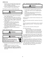

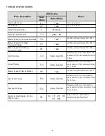


30
PRIMARY LIMIT
CONTROL
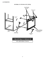
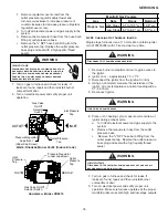
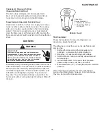
Primary Limit Control Location
(90% Upflow Furnace Shown, Counterflow
Similar)
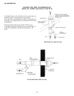
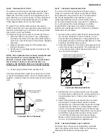
The following drawing illustrates the style of limit switches
used on the 90% furnaces.
ENCLOSED DISK
FRONT VIEW
SIDE VIEW
Primary Limit Control Style
(90% Furnaces)
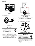
WARNING
HIGH VOLTAGE
Disconnect ALL power before servicing or in
-
stalling this unit. Multiple power sources may
be present. Failure to do so may cause proper
-
ty damage, personal injury or death.
1. Remove burner compartment door to gain access to
the primary limit.
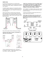
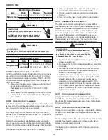
2. Remove low voltage wires at limit control terminals.
3. With an ohmmeter, test between these two terminals
as shown in the following drawing. The ohmmeter
should read continuous unless heat exchanger
temperature is above limit control setting. If not as
above, replace the control.
VOLT / OHM
METER
COLOR
IDENTIFYING
TAB
Testing Primary Limit Control
(90% Furnaces)
4. After completing check and/or replacement of primary
limit control, reinstall burner compartment door.
5. Turn on electrical power and verify proper unit
operation.
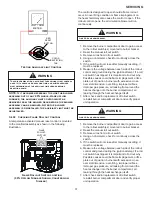
S-301 Checking Auxiliary Limit Control
LIMIT
AUXILIARY LIMIT
CONTROL
AUXILIARY LIMIT
CONTROL
BLOWER HOUSING
Auxiliary Limit Control Location
WARNING
HIGH VOLTAGE
Disconnect ALL power before servicing or in
-
stalling this unit. Multiple power sources may
be present. Failure to do so may cause proper
-
ty damage, personal injury or death.
1. Remove blower compartment door to gain access to
the auxiliary.
2. Remove the wires from the auxiliary limit control
terminals.
3. Using an ohmmeter, test for continuity across the two
terminals.
SERVICING


