D2CND0 D2CND0 D2TND0
D2TND0 D2TND024A4AA
Wall-mounted condensing boiler
ESIE17-09 / 2017.11
Servicing manual
6
Structure and components of models
D2CND024A1AA, D2CND024A4AA
2.3
Appliance structure and components
1
27
2
3
4
5
6
7
8
9
14
15
12
13
19
26
10
11
16
17
18
20
21
22
23
24
25
figure-6a, Structure and components of models D2CND024A1AA and
D2CND024A4AA
Key
1 Automatic air vent (heat exchanger)
2 Flow temperature sensor
3 Expansion vessel (8 litres)
4 Gas valve
5 Heat exchanger
6 3 way valve stepper motor
7 Domestic hot water temperature sensor
8 Plate heat exchanger
9 Safety valve (3 bar)
10 Condensate trap
11 Ignition transformer
12 Flue gas temperature sensor
13 Burnerhood
14 Ignition electrode
15 Ionization electrode
16 High limit thermostat
17 Fan
18 Return temperature sensor
19 Silencer
20 Automatic air vent (pump)
21 Water pressure sensor
22 By-pass
23 Boiler pump
24 Domestic hot water flow sensor
25 Domestic hot water flow limiter
26 Internal filling valve (Only in model D2CND024A1AA)
27 Flue gas adapter
Structure and components of models
D2TND024A4AA, D2TND018A4AA and D2TND012A4AA
1
2
3
4
5
6
7
8
9
10
11
12
13
14
15
16
17
18
19
20
21
figure-6b, Structure and components of models D2TND024A4AA,
D2TND018A4AA and D2TND012A4AA
Key
1 Automatic air vent (heat exchanger)
2 Flow temperature sensor
3 Expansion vessel (8 litres)
4 Gas valve
5 Heat exchanger
6 3 way valve stepper motor
7 Safety valve (3 bar)
8 Condensate trap
9 Flue gas temperature sensor
10 Burnerhood
11 Ignition electrode
12 Ionization electrode
13 High limit thermostat
14 Fan
15 Return temperature sensor
16 Silencer
17 Automatic air vent (pump)
18 Water pressure sensor
19 By-pass
20 Boiler pump
21 Flue gas adapter
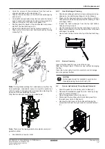
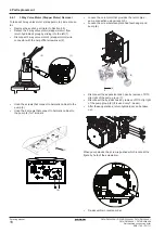
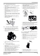
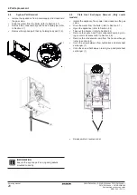
2 Appliance information


