D2CND0 D2CND0 D2TND0
D2TND0 D2TND024A4AA
Wall-mounted condensing boiler
ESIE17-09 / 2017.11
Servicing manual
24
5.3
Combining the Boiler With Options
Optional equipments are connected to the connectors which
are located on the outside of the switch box. Do not open the
switch box to connect optional equipment.
Temperature Control Units
Connector Connection
Solar NTC sensor
X1M
1-2
Opentherm room thermostat
X1M
3-4
Outdoor sensor
X1M
5-6
Boiler sensor
X1M
7-8
Ext. power output (230 VAC) X2M
3-4
On-Off room thermostat
X2M
5-6
Solar stop contact
X2M
7-8
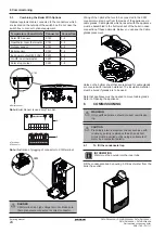
Wiring of the options that are to be connected to the X2M
connector must pop out from the inside of the appliance via
cable glands. Cable glands which are sent with the appliance
must be assembled to the bottom sheet of the boiler in case
connection of these optionals. Below, you can see the Cable
glands placement.
Holes on the bottom sheet that are reserved for cable glands
are covered with insulation material. The insulation material
must be bored if glands are to be used.
Note that appliance must be opened to mount cable glands.
Refer to ‘Opening the appliance’ .
6 Commissioning
A
X1M
8
1
a
PG 7
PG 7
PG 9
PG 9
(1-2)
(3-4)
(5-6)
(7-8)
a
b
X2M
8
1
6 COMMISSIONING
Only qualified persons should conduct commission
-
ing.
WARNING
Preliminary electrical system checks such as earth
continuity, polarity, resistance to earth and short
circuit must be carried out by using a suitable test
meter by a competent person.
CAUTION
6.1
To fill the condensate trap
Fill the condensate trap by pouring 0.2 litres of water from the
boiler flue outlet.
Water must be poured into the inner tube.
INFORMATION
Note:
Illustration of plugging of connector to X1M terminal.
X2M terminal is a high voltage terminal. Make sure
that optionalsare connected to correct connector.
DANGER
a Terminal
b Connector
a Boiler sensor
Note:
Boiler Sensor is used only T-model.


