D2CND0 D2CND0 D2TND0
D2TND0 D2TND024A4AA
Wall-mounted condensing boiler
ESIE17-09 / 2017.11
Servicing manual
22
4.11
PCB Removal
4.11.1 Daikin Eye and Push Button Removal
4.11.2 Terminal (X1M) Removal
•
Isolate the appliance from power supply and closedown
the gas valve.
•
Open the appliance (refer to Section 4.2).
•
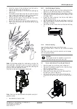
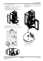
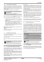
Undo the 4 screws that connect the control panel back
cover to control panel.(1)
•
Disconnect all cable connection that insert to PCB.
•
Disconnect the cables from on the back cover bracket
(refer to Section 4.2).
•
Undo terminal (X2M) cover’s screw and take out the
terminal and its cover from control panel cover (2).
•
Remove the back cover paying attention to the its pawls
which locate between the back cover and the control
panel (3).
•
Undo the cable support’s 3 screws holding the main pcb
and remove the cable support (4).
•
Unscrew the 3 screws that connect PCB and control
panel(5).
•
Isolate the appliance from power supply and closedown
the gas valve.
•
Open the appliance (refer to Section 4.2).
•
Take out the PCB (refer to Section 4.11).
•
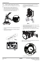
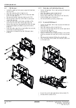
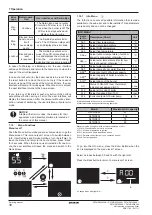
Remove the buttons from back of the control panel (6).
•
Unscrew Daikin eye’s 2 screws (7).
•
Disconnect Daikin eye’s wire connector (8).
•
Isolate the appliance from power supply and closedown
the gas valve.
•
Open the appliance (refer to Section 4.2)
•
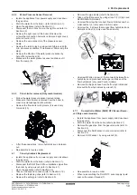
Undo the 4 screws that connect the control panel back
cover to control panel.(1)
•
Undo terminal’s (X2M) screw (2).
•
Remove the back cover, paying attention to the pawls
which are between the back cover and the control panel
(3).
•
Disconnect the terminal’s (X1M) wire connector (9).
•
Undo the screws that connect the terminal (X1M) and
control panel (10).
•
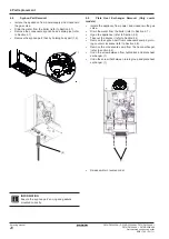
Ensure the control panel gasket mounted correctly (11).
•
Re-assemble in reverse order.
4 Part replacement
(5)
(6)
(7)
(10)
(8)
(9)
(1)
(2)
(4)
(3)
(11)


