background image

General Outline: Altherma

ESIE06-03

1–10

Part 1 – System Outline

3

11

4

5

1.5

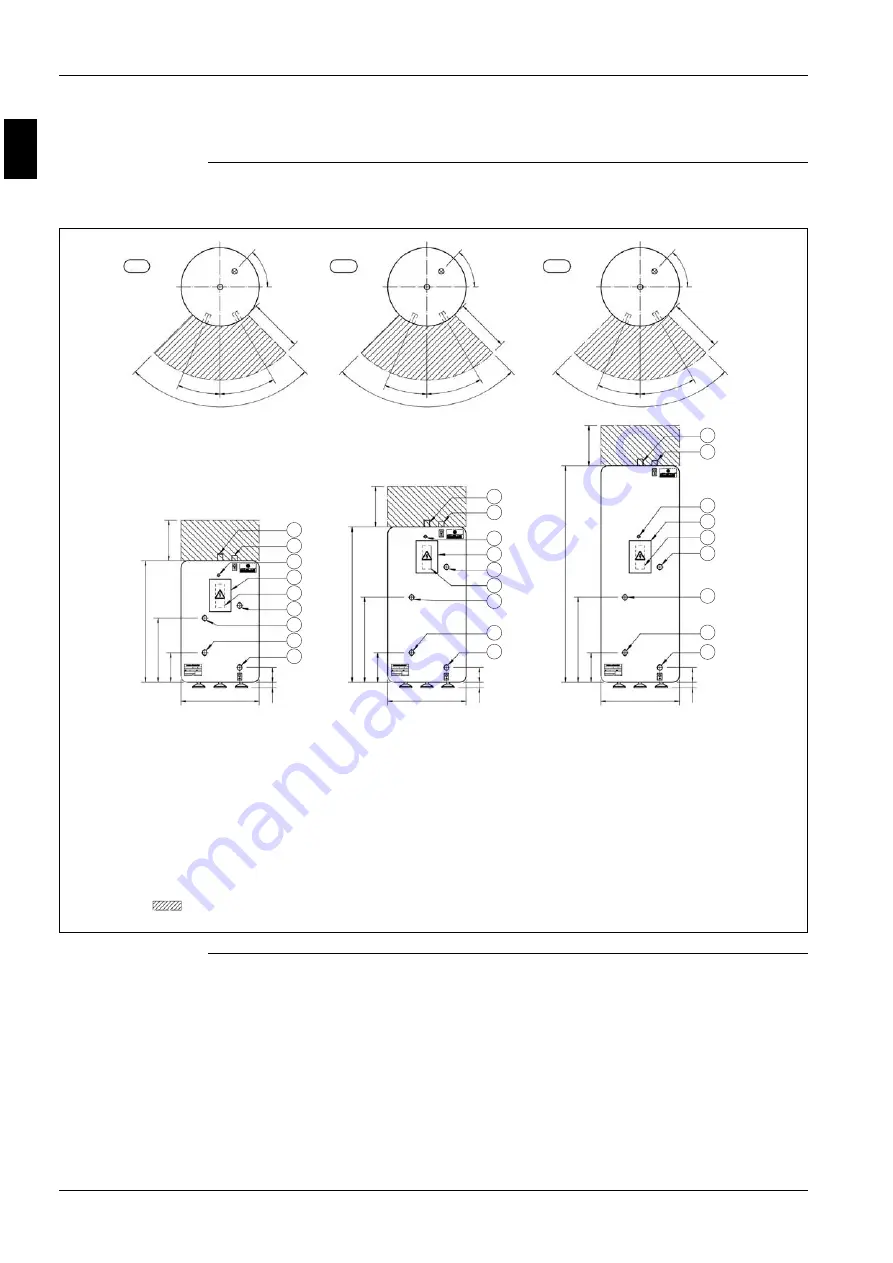
EKSWW150~300V3: Outlook and Dimensions - Service Space

Outlook and 
dimensions - 
Service space

The illustration below shows the outlook and the dimensions of the unit (mm).

580

0-40

1

1

0

220

475

300

900

580

0-40

1

1

0

220

630

300

11

5

0

580

0-40

1

1

0

220

630

300

1600

23°

90°

30°

23°

90°

30°

23°

90°

30°

47°

400

47°

400

47°

400

150 L

200 L

300 L

8

2

8

8

2

9

6

7

3

4

5

1

2

9

6

3

7

4

5

1

9

6

7

3

4

5

1

Required service space 
around the tank

Содержание Altherma EKHBH Series

Страница 1: ...em Outline What is in this part This part contains the following chapters Chapter See page 1 General Outline Altherma 1 3 2 Specifications 1 15 3 Functional Diagrams 1 21 4 Piping Diagrams 1 27 5 Switch Box Layout 1 33 6 Wiring Diagrams 1 39 7 PCB Layout 1 51 ...

Страница 2: ...ESIE06 03 1 2 Part 1 System Outline 3 1 1 5 ...

Страница 3: ...cal limitations and limits of operation General outline This chapter contains the following general outlines General outline See page 1 2 ERYQ005 007AAV3N Outlook and Dimensions 1 4 1 3 EKHBH007A Outlook and Dimensions 1 6 1 4 EKHBX007A Outlook and Dimensions 1 8 1 5 EKSWW150 300V3 Outlook and Dimensions Service Space 1 10 1 6 ERYQ005 007AAV3N Installation and Service Space 1 12 1 7 EKHBH X 007A I...

Страница 4: ...V3N Outlook and Dimensions Outlook and dimensions The illustration below shows the outlook and the dimensions of the unit mm Installation and service space See page 1 12 9 10 1 2 3 4 5 7 825 78 580 325 124 155 18 30 89 64 160 2 36 300 330 25 10 350 8 6 In case of removing stop valve cover ...

Страница 5: ...erent components of the unit No Component 1 Brand name label 2 Name plate 3 Wiring inlet 4 Terminal strip with earth terminal 5 Outdoor air temperature thermistor 6 Gas stop valve φ15 9CuT 7 Service port 8 Liquid stop valve φ6 4CuT 9 Drain outlet I D φ15 9 hose for connection 10 4 holes for anchor bolts M8 or M10 ...

Страница 6: ...llustration below shows the outlook and the dimensions of the unit mm Installation and service space See page 1 13 8 18 11 10 7 1 2 9 16 19 16 16 3 13 5 4 12 15 14 Service door 1 Female BSP 1 Male BSP 286 2xØ 12 2xØ 12 2 x Ø 3 0 Ø 16 CLOSED 361 OPEN 553 20 286 361 895 600 133 80 100 487 431 170 67 46 42 93 100 65 28 287 236 97 360 36 6 ...

Страница 7: ...ection 1e M BSP 5 Power supply intake sanitary warm water tank 6 Drain fill valve 7 Air purge 8 Expansion vessel nipple 9 Blow off valve 10 Pressure gauge 11 Waterfilter 12 Suction pipe connection φ15 9 flare connection 13 Liquid pipe connection φ9 52 flare connection 14 Shut off valves delivered with unit 15 Thermistor connection sanitary warm water tank 16 Holes for fixation 17 Blow off drain 18...

Страница 8: ... shows the outlook and the dimensions of the unit mm Installation and service space See page 1 13 8 18 5 11 7 1 2 15 10 9 16 19 16 3 13 4 14 Service door 1 Female BSP 1 Male BSP 286 2xØ 12 Ø 12 Ø 32 CLOSED 461 OPEN 653 20 286 461 936 895 731 13 80 337 125 487 286 487 153 122 10 12 40 31 54 53 156 62 58 144 28 6 Ø 46 12 17 152 148 Dimensions wallbracket ...

Страница 9: ...ection 1e M BSP 5 Power supply intake sanitary warm water tank 6 Drain fill valve 7 Air purge 8 Expansion vessel nipple 9 Blow off valve 10 Pressure gauge 11 Waterfilter 12 Suction pipe connection φ15 9 flare connection 13 Liquid pipe connection φ9 52 flare connection 14 Shut off valves delivered with unit 15 Thermistor connection sanitary warm water tank 16 Holes for fixation 17 Blow off drain 18...

Страница 10: ...ons Service space The illustration below shows the outlook and the dimensions of the unit mm 580 0 40 110 220 475 300 900 580 0 40 110 220 630 300 1150 580 0 40 110 220 630 300 1600 23 90 30 23 90 30 23 90 30 4 7 4 0 0 4 7 4 0 0 4 7 4 0 0 150 L 200 L 300 L 8 2 8 8 2 9 6 7 3 4 5 1 2 9 6 3 7 4 5 1 9 6 7 3 4 5 1 Required service space around the tank ...

Страница 11: ...ntains the different components of the unit No Component 1 Water mains IN female 3 4 BSP 2 Water mains OUT female 3 4 BSP 3 Thermistor connection female 1 2 BSP 4 Flow from Hydro box female 3 4 BSP 5 Return to Hydro box female 3 4 BSP 6 Switchbox 7 Clixon 8 Connection female 1 2 BSP 9 Power entrance ...

Страница 12: ... in the path of the outdoor unit air intake or exhaust airflow follow the installation guidelines below P For any of the installation patterns below the wall height on the exhaust side should be 1200 mm or less Wall facing one side unit mm Walls facing two sides unit mm Walls facing three sides unit mm Remark P Back to back 300 mm P Front to front 5000 mm 100 350 1200 50 50 350 100 100 350 50 ...

Страница 13: ... Space EKHBH The illustration below shows the minimum service space for service and ventilation EKHBX The illustration below shows the minimum service space for service and ventilation A B Setup 1 200 400 Setup 2 350 200 A B 250 500 172 460 400 200 A B Setup 1 200 400 Setup 2 350 200 A B 250 500 235 460 400 200 ...

Страница 14: ...supplied with the sanitary tanks is 12 m in length May not be changed Sanitary tank INDOOR OUTDOOR Thermostat G I E 2 way valve 3 way valve A B C F J D Heat emitters H outdoor indoor Total system 20 m outdoor unit can be above or below the hydro box Piping R410A Piping water Power supply Communication A B C D E F G H I J ERYQ005ABV3 3 A 30m 3 m 10 m depend on instal lation depend on instal lation ...

Страница 15: ...t Is in This Chapter Introduction This chapter contains the following information P Technical specifications P Electrical specifications Altherma This chapter contains the following specifications Specifications See page 2 2 ERYQ005 007 1 16 2 3 EKHBH and EKHBX 1 18 2 4 EKSWW150 300V3 Z2 1 20 ...

Страница 16: ... Xa 8 Fin Type WF fin Treatment Anti corrosion treatment PE Fan Type Propeller Discharge direction Horizontal Quantity 1 Air flow rate nominal at 230 V Heating high Heating low Cooling high Cooling low Motor Quantity 1 Output 53 W Compressor Quantity 1 Motor Model 2YC63BXD C Type Hermetically sealed swing compressor Output 1920 W Operation range see Altherma operation manual Heating Min 20 C DB Ma...

Страница 17: ...15 m Max interunit level difference 20 m Defrost method Reverse cycle Defrost control Sensor for outdoor heat exchanger temperature Capacity control method Inverter controlled Standard accessories Item Installation manual drain plug Quantity 1 Specification ERYQ005 007 Specification ERYQ00 Power supply Name V1 Phase 1 Frequency 50 Hz Voltage 220 V 240 V Voltage range Minimum 10 V Maximum 10 V Curr...

Страница 18: ...Pa 46 5 kPa 44 4 kPa Nominal ESP unit Heating 46 5 kPa 40 1 kPa 29 0 kPa 46 5 kPa 40 1 kPa 29 0 kPa Power input 130 W Water side Heat exchanger Type Brazed plate Quantity 1 Water volume 0 67 l Water flow rate Min 12 l min 12 l min 12 l min 12 l min 12 l min 12 l min Water flow rate Nom Cooling 14 7 l min 16 5 l min 17 6 l min Water flow rate Nom Heating 16 5 l min 19 6 l min 24 2 l min 16 5 l min ...

Страница 19: ...for the 3V3 model which has only 1 capacity step Specification EKHBH EKHBX EKHBH007A EKHBH007A EKHBH007A EKHBX007 EKHBX007 EKHBX007 Outdoor units ERYQ005A ERYQ006A ERYQ007A ERYQ005A ERYQ006A ERYQ007A Electric heater Type 3V3 6V3 6W1 6T1 9W1 9T1 Power supply Phase 1 1 3N 3 3N 3 Frequency 50 Hz Voltage 230 V 230 V 400 V 230 V 400 V 230 V Current Running current 13 A 26 A 8 6 A 15 A 13 A 23 A Zmax Li...

Страница 20: ...40 kg 49 kg 64 kg 49 kg 64 kg Packing Material EPS Carton Weight 3 kg 4 kg 5 kg 4 kg 5 kg Main components Tank Water volume 150 l 200 l 300 l 200 l 300 l Material Stainless steel DIN 1 4521 Max temperature 85 C Max water pressure 10 bar Insulation Material Polyurethane foam Insulation Min thickness 40 mm Heat exchanger Quantity 1 Material Stainless steel DIN 1 4401 Booster heater Quantity 1 Capaci...

Страница 21: ...This chapter contains the following information P Overview complete system P Electrical connection diagram P Pipe connection diameters Functional diagrams This chapter contains the following functional diagrams Functional diagram See page 3 2 Complete System 1 22 3 3 Electrical Connection Diagram 1 24 3 4 Pipe Connection Diameters 1 25 ...

Страница 22: ...03 1 22 Part 1 System Outline 3 1 1 4 5 3 2 Complete System R4T H 2 O t R5T t R3T t R2T t R1T t M M FCU1 T1 M1 T1 M 2 1 3 4 12 11 10 9 8 7 5 6 5 13 14 15 16 17 19 24 27 28 26 25 20 5 23 22 21 2 18 refrigerant flow cooling heating ...

Страница 23: ...mulator 10 Compressor 11 Discharge pipe thermistor 12 4 way valve ON heating 13 Expansion vessel 14 Pump 15 Air purge valve 16 Drain valve 17 Flow switch 18 Backup heater 19 Outlet 20 Inlet 21 Manometer 22 Fill and drain valve 23 Pressure relief valve 24 3 way valve for sanitary water tank 25 Booster heater 26 SWW tank 27 2 way valve for cooling mode 28 By pass valve R1T Outlet water Heatexchanger...

Страница 24: ...ooling mode M3S when EKSWW is installed 2way valve 3way valve Optional parts OUTDOOR UNIT HYDRO BOX X1M L N earth booster heater power supply 3kW 400V or 230V earth Optional power supply backup heater power supply 3 6 9kW 400V or 230V earth unit power supply 230V earth X2M 1 2 3 earth X1M 9 10 11 earth X1M 7 8 earth X1M 13 15 17 23 X1M 19 20 user interface NO valve X1M 16 18 NO valve X1M 14 18 X9A...

Страница 25: ... box water side The table below contains the water inlet outlet connection diameters 1 MBSP male British standard pipe 2 FBSP female British standard pipe Model Gas pipe flare Liquid pipe flare ERYQ005ABV3 15 9 mm 6 4 mm ERYQ006ABV3 ERYQ007ABV3 Model Gas pipe flare Liquid pipe flare EKHBH007A 15 9 mm 6 4 mm EKHBX007A Model Gas pipe flare Liquid pipe flare EKHBH007A 1 inch MBSP 1 1 inch MBSP EKHBX0...

Страница 26: ...Functional Diagrams ESIE06 03 1 26 Part 1 System Outline 3 1 1 4 5 ...

Страница 27: ...art 1 4 Piping Diagrams 4 1 What Is in This Chapter Introduction This chapter contains the following information P Piping diagrams Piping diagrams This chapter contains the following piping diagrams Functional diagram See page 4 2 ERYQ005 007 1 28 4 3 EKHBH X 1 30 ...

Страница 28: ...10 7 7 3 4 5 6 8 8 9 11 11 7 9 CuT 7 9 CuT 7 9 CuT 7 9 CuT 7 9 CuT 12 7 CuT 12 7 CuT 12 7 CuT 12 7 CuT 12 7 CuT 7 9 CuT 7 9 CuT 12 7 CuT 6 4 CuT 6 4 CuT 6 4 CuT 6 4 CuT 6 4 CuT 6 4 CuT 15 9 CuT 7 9 CuT 7 9 CuT 7 9 CuT 7 9 CuT 4 0 CuT 7 9 CuT 4 0 CuT 4 0 CuT 4 0 CuT Outdoor Unit refrigerant flow cooling heating ...

Страница 29: ...Heat exchanger thermistor 3 Capillary Tube 1 4 Capillary Tube 2 5 Capillary Tube 3 6 Capillary Tube 4 7 Muffler with filter 8 Filter 9 Motor operated valve 10 Liquid stop valve 11 Field piping 12 Gas stop valve with service port 13 Accumulator 14 Compressor 15 Discharge pipe thermistor 16 Muffler 17 4 way valve on heating 18 Propeller fan 19 Outdoor air temperature thermistor ...

Страница 30: ...8 4 9 10 2 FIELD INSTALLATION FIELD INSTALLATION OPTION BACKUP HEATER OUTDOOR UNIT REFR OUT EVAPORATOR CONDENSOR WATER INLET R4T t R3T t WATER OUTLET REFR OUT REFR IN REFR IN INLET OUTLET REFRIGERANT SIDE COOLING EKHBX HEATING EKHBX EKHBH OVERVIEW REFR SIDE WATER SIDE WATER SIDE R1T t R2T t ...

Страница 31: ...he functional diagrams No Name 1 Filter 2 Shut off valve 3 Pressure gauge 4 Drain valve 5 Safety valve 6 Expansion vessel 7 Pump 8 Air purge 9 Electric heater body 10 Flowswitch R1T Outlet water heat exchanger thermistor R2T Outlet water backup heater thermistor R3T Refrigerant liquid side thermistor R4T Inlet water thermistor ...

Страница 32: ...Piping Diagrams ESIE06 03 1 32 Part 1 System Outline 3 1 1 4 5 ...

Страница 33: ...t 1 5 Switch Box Layout 5 1 What Is in This Chapter Introduction This chapter shows the switch box components Altherma This chapter contains the following switch box layouts Switch box layout See page 5 2 ERYQ005 007 1 34 5 3 EKHBH X 005 007A 1 36 5 4 EKSWW V3 Z2 1 37 ...

Страница 34: ...tch Box Layout ESIE06 03 1 34 Part 1 System Outline 3 1 1 4 5 5 2 ERYQ005 007 The illustration below shows the outdoor switch box 1 layout Item Description PCB1 Printed circuit board main L1R Reactor coil ...

Страница 35: ...h Box Layout Part 1 System Outline 1 35 3 1 4 5 The illustration below shows the outdoor switch box 2 layout Item Description PCB2 Printed circuit board X1M Terminal strip Power supply X2M Terminal strip Communication ...

Страница 36: ...t Item Description K1M Contactor backup heater step 1 K2M Contactor backup heater step 2 K3M Contactor booster heater X1M Terminal strip nr 1 6 power supply backup heater X2M Terminal strip nr 7 25 power supply interconnection wiring F1B Fuse backup heater F2B Fuse booster heater PCB A1P Printed circuit board TR1 Transformer 220 V 24 V ...

Страница 37: ...illustration below shows the switch box layout 1 Remark Internal connection of Booster heater 3 kW 400 V is slightly different Item Description X1M Terminal strip nr 1 2 power supply booster heater Q2L Thermal protector booster heater connection nr 3 4 E4H Booster heater 3 kW 230 V 1 ...

Страница 38: ...Switch Box Layout ESIE06 03 1 38 Part 1 System Outline 3 1 1 4 5 ...

Страница 39: ...contains the wiring diagrams of the outdoor hydro box and sanitary water tank Altherma This chapter contains the following wiring diagrams Wiring diagram See page 6 2 EKHBH X 005 007A3V3 1 40 6 3 EKHBH X 005 007A6V3 1 42 6 4 EKHBH X 005 007A6W1 A9W1 1 44 6 5 EKHBH X 005 007A6T1 A9T1 1 46 6 6 ERYQ005 007AAV3N 1 48 6 7 EKSWW150 300V3 Z2 1 50 ...

Страница 40: ... DEPENDENT ON MODEL FIELD WIRING OPTION PCB WIRE COLOR only for EKSWW option only for EKHB 00 A3V3 POWER SUPPLY SEE NOTE 2 OUTDOOR UNIT A1P sanitary tank only for EKSWW option only for EKHB 00 A3V3 or 6V3 only for EKHB 00 A3V3 NC valve NO valve 230V AC supply from PCB A2P thermostat sanitary tank heating coolong on off only for EKHB 00 A6V3 only for EKSWW option only for EKSWW option A3P ...

Страница 41: ...rmistor F1B Fuse backup heater R3T Refrigerant liquid side thermistor F2B Fuse booster heater R4T Inlet water thermistor FU1 Fuse 3 15 A T 250 V R5T SWW thermistor K1M Contactor backup heater step 1 S1L Flowswitch K2M Contactor backup heater step 2 TR1 Transformer 24 V for PCB K3M Contactor booster heater V1S Spark suppression 1 M1P Pump V2S Spark suppression 2 1 This wiring diagram only applies t...

Страница 42: ...wiring diagram of the unit WIRING DEPENDENT ON MODEL FIELD WIRING OPTION PCB WIRE COLOR only for EKSWW option POWER SUPPLY SEE NOTE 2 OUTDOOR UNIT A1P sanitary tank only for EKSWW option only for EKHB 00 A3V3 or 6V3 NC valve NO valve 230V AC supply from PCB A2P thermostat sanitary tank heating coolong on off only for EKSWW option only for EKSWW option A3P ...

Страница 43: ... heater R3T Refrigerant liquid side thermistor F2B Fuse booster heater R4T Inlet water thermistor FU1 Fuse 3 15 A T 250 V R5T SWW thermistor K1M Contactor backup heater step 1 S1L Flowswitch K2M Contactor backup heater step 2 TR1 Transformer 24 V for PCB K3M Contactor booster heater V1S Spark suppression 1 K4M Contactor backup heater V2S Spark suppression 2 M1P Pump X1M Terminal block 1 This wirin...

Страница 44: ... of the unit WIRING DEPENDENT ON MODEL FIELD WIRING OPTION PCB WIRE COLOR only for EKSWW V3 option only for EKSWW Z2 option POWER SUPPLY SEE NOTE 2 OUTDOOR UNIT A1P sanitary tank only for EKSWW option NC valve NO valve 230V AC supply from PCB A2P A3P thermostat sanitary tank sanitary tank heating coolong on off only for EKSWW option only for EKSWW option ...

Страница 45: ... F2B Fuse booster heater R4T Inlet water thermistor FU1 Fuse 3 15 A T 250 V R5T SWW thermistor K1M Contactor backup heater step 1 S1L Flowswitch K2M Contactor backup heater step 2 TR1 Transformer 24 V for PCB K3M Contactor booster heater V1S Spark suppression 1 K4M Contactor backup heater V2S Spark suppression 2 M1P Pump X1M Terminal block M2S 2 way valve for cooling mode 1 This wiring diagram onl...

Страница 46: ...ws the wiring diagram of the unit WIRING DEPENDENT ON MODEL FIELD WIRING OPTION PCB WIRE COLOR only for EKSWW option POWER SUPPLY SEE NOTE 2 OUTDOOR UNIT A1P sanitary tank only for EKSWW option NC valve NO valve 230V AC supply from PCB A2P A3P thermostat sanitary tank heating coolong on off only for EKSWW option only for EKSWW option ...

Страница 47: ... F2B Fuse booster heater R4T Inlet water thermistor FU1 Fuse 3 15 A T 250 V R5T SWW thermistor K1M Contactor backup heater step 1 S1L Flowswitch K2M Contactor backup heater step 2 TR1 Transformer 24 V for PCB K3M Contactor booster heater V1S Spark suppression 1 K4M Contactor backup heater V2S Spark suppression 2 M1P Pump X1M Terminal block M2S 2 way valve for cooling mode 1 This wiring diagram onl...

Страница 48: ...1 48 Part 1 System Outline 3 1 1 4 5 6 6 ERYQ005 007AAV3N Wiring diagram The illustration below shows the wiring diagram of the unit indoor outdoor SHEET METAL FIELD WIRING OUTDOOR DISCHARGE CONDENSER TO INDOOR UNIT POWER SUPPLY ...

Страница 49: ...ctor L Live SA2 Surge arrester L1R Reactor Sheet metal Terminal strip fixed plate LEDA Pilot lamp SW1 Forced operation On Off SW SW1 M1C Fan motor SW4 Local setting SW SW4 M1F Fan motor V2 V3 V5 V9 V100 Varistor MRC W MRM10 MRM20 Magnetic relay X1M X2M Terminal strip Y1E Electronic expansion valve coil N Neutral Y1R Reversing solenoid valve coil PCB1 PCB2 Printed circuit board Z1C Z7C Ferrite core...

Страница 50: ...Wiring Diagrams ESIE06 03 1 50 Part 1 System Outline 3 1 1 4 5 6 7 EKSWW150 300V3 Z2 Wiring diagram The illustration below shows the wiring diagram of the sanitary water tank RESET ...

Страница 51: ...at Is in This Chapter Introduction This chapter contains the following information P It describes which unit uses which PCB types P It shows the PCB connectors Outdoor units This chapter contains the following PCB layouts PCB layout See page 7 2 ERYQ005 007AAV3N 1 52 7 3 EKHBH X 1 56 ...

Страница 52: ...PCB Layout ESIE06 03 1 52 Part 1 System Outline 3 1 1 4 5 7 2 ERYQ005 007AAV3N Outdoor PCB 1 main The illustration below shows the PCB connectors ...

Страница 53: ...rminal strip Communication S20 Y1E Electronic expansion valve S40 Q1L Overload protector S51 PCB2 S52 Printed circuit board S70 M1F Fan motor S80 Y1R 4 Way valve S90 R1T Thermistor Discharge R2T Thermistor Condensor R3T Thermistor Outdoor S101 PCB2 S102 Printed circuit board AC1 X1M Terminal strip Power supply AC2 HR1 L1R Reactor coil HR2 UVW M1C Inverter compressor ...

Страница 54: ...PCB Layout ESIE06 03 1 54 Part 1 System Outline 3 1 1 4 5 Outdoor PCB 2 The illustration below shows the PCB connectors ...

Страница 55: ...ne 1 55 3 1 4 5 Connectors The table below describes the PCB connectors Connector Connected to Description S2 Not applicable S52 PCB 1 S51 Printed circuit board S102 PCB 1 S101 Printed circuit board SW1 Forced operation On Off SW4 Dip switch ...

Страница 56: ...PCB Layout ESIE06 03 1 56 Part 1 System Outline 3 1 1 4 5 7 3 EKHBH X Main PCB The illustration below shows the PCB connectors ...

Страница 57: ...rmistor X7A R3T Refrigerant liquid side thermistor X8A R4T Inlet water thermistor X9A R5T SWW thermistor EKSWW option X10A VRV checker connection X11A K1M Contactor backup heater step 1 X12A K2M Contactor backup heater step 2 X13A K3M Contactor booster heater X14A Not Applicable X15A M1P Pump X16A M3S 19 20 3 way valve floorheating sanitary warm water X17A PCB A3P 13 15 17 23 Thermostat Field supp...

Страница 58: ...PCB Layout ESIE06 03 1 58 Part 1 System Outline 3 1 1 4 5 ...

Страница 59: ...mation on the functions used to control the system Understanding these functions is vital when diagnosing a malfunction that is related to the functional control Overview This part contains the following chapters Chapter See page 1 General Functionality 2 3 2 Hydro box Functional Concept 2 7 3 Outdoor Unit Functional Concept 2 11 ...

Страница 60: ...ESIE06 03 2 2 Part 2 Functional Description 3 1 2 5 ...

Страница 61: ...t related to the compressor frequency control outdoor unit fan control and expansion valve control These functions have been programmed to ensure the unit s reliability and lifetime enable the operation in case of malfunction Overview This chapter contains the following topics Topic See page 1 2 Preheating Operation 2 4 1 3 Four Way Valve Switching 2 5 1 4 Freeze up Protection Control 2 6 ...

Страница 62: ...e internal temperature of PM1 Detail Outside temperature 10 C Control A preheating for normal state Outside temperature 10 C Control B preheating for increased capacity Control A P ON condition Discharge pipe temperature 6 C Fin temperature 85 C P OFF condition Discharge pipe temperature 8 C Fin temperature 90 C Control B P ON condition Discharge pipe temperature 10 5 C Fin temperature 85 C P OFF ...

Страница 63: ... be conducted and during cooling and defrosting current must not be conducted In order to eliminate the switching sound as the four way valve coil switches from ON to OFF when the heating is stopped the delay switch of the four way valve must be carried out after the operation stopped Detail The OFF delay of four way valve Energize the coil for 150 sec after unit operation is stopped ...

Страница 64: ...cy limitation and then prevent freezing of the indoor heat exchanger The signal from the hydro box must be divided into the zones as the followings Conditions for start controlling Judge the controlling start with the indoor heat exchanger temperature after 2 sec from operation start Control in each zone A Heat exchanger thermistor temperature Return Reset zone Up zone Keep zone Drooping zone Stop...

Страница 65: ...ydro box Functional Concept 2 1 What Is in This Chapter Introduction This chapter will explain more details about the various functions that are programmed for the hydro box Overview This chapter contains the following topics Topic See page 2 2 Defrost Control 2 8 2 3 Forced Operation Mode 2 9 ...

Страница 66: ... outdoor air temperature and heat exchanger temperature Under the conditions that the system is in heating operation 6 minutes after the compressor is started and more than 44 minutes of accumulated time pass since the start of the operation or ending the defrosting Conditions for canceling defrost The judgment must be made with heat exchanger temperature 4 C 12 C Frequency Compressor Four way val...

Страница 67: ... The forced operation is allowed when the above and conditions are met Starting adjustment If the forced operation switch is pressed as the above conditions are met P Command frequency 55 Hz cooling 66 Hz heating P Electronic expansion valve opening It depends on the capacity of the operating hydro box P Outdoor unit adjustment Compressor is in operation P Hydro box adjustment The command of force...

Страница 68: ...Hydro box Functional Concept ESIE06 03 2 10 Part 2 Functional Description 3 1 2 4 5 ...

Страница 69: ...0A inverter outdoor units Overview This chapter contains the following topics Topic See page 3 2 Frequency Principle 2 12 3 3 Frequency Control 2 14 3 4 Controls at Mode Changing Start up 2 16 3 5 Discharge Pipe Temperature Control 2 17 3 6 Input Current Control 2 18 3 7 Heating Peak cut Control 2 19 3 8 Fan Control 2 20 3 9 Liquid Compression Protection Function 2 2 21 3 10 Low Hz High Pressure L...

Страница 70: ...version principle Drawing of inverter The following drawing shows a schematic view of the inverter principle Phase Description 1 The supplied AC power source is converted into the DC power source for the present 2 The DC power source is reconverted into the three phase AC power source with varia ble frequency P When the frequency increases the rotation speed of the compressor increases resulting i...

Страница 71: ...ture P Energy saving heating and cooling Once the set temperature is reached the energy saving operation enables to maintain the room temperature at low power Frequency limits The following table shows the functions that define the minimum and maximum frequency 60 120 300 T C Discharge temperature inverter normal heat pump Start seconds Frequency limits Limited during the activation of following f...

Страница 72: ...iting defrost control time P Forced cooling P Indoor frequency command P Determine upper limit frequency Set a minimum value as an upper limit frequency among the frequency upper limits of the following functions Compressor protection input current discharge pipes Low Hz high pressure peak cutting freeze prevention defrost P Determine lower limit frequency Set a maximum value as an lower limit fre...

Страница 73: ...ncy previously calculated P I control If the operating frequency is not change more than a certain fixed time adjust the frequency up and down according to the D value obtaining the fixed D value When the D value is small lower the frequency When the D value is large increase the frequency P Limit of frequency variation width When the difference between input current and input current drooping val...

Страница 74: ... compressor halted P The MRC W turns OFF when the compressor starts for cooling after the MRC W has been ON with compressor running P The compressor starts for the first time after reset P The compressor starts after suspension caused by the trouble of cooling heating changeover Set the lower limit frequency to 48 Hz for 70 seconds with any conditions 1 through 4 above 3 minutes stand by Prohibit ...

Страница 75: ...imit is set to keep this temperature from going up further Divide the zone Management within the zones 71 class A 120 B 111 C 109 D 107 E 107 A C B C C C D C E C Reset zone Keep zone Drooping zone Stop zone Discharge pipe temperature Zone Control contents Stop zone When the temperature reaches the stop zone stop the compressor and cor rect abnormality Drooping zone Start the timer and the frequenc...

Страница 76: ...quency is pulled down by 2Hz every second until it reaches the steady zone P Keep zone P The present maximum frequency goes on P Reset zone P Limit of the frequency is cancelled P Stop zone P After 2 5 s in this zone the compressor is stopped Limitation of current drooping and stop value according to the outdoor air temperature P In case the operation mode is cooling The current droops when outdoo...

Страница 77: ...limitation and prevent abnormal high pressure the signal from the hydro box must be divided as follows Conditions for start controlling Judge the controlling start with the indoor heat exchanger temperature after 5 sec from operation start Control in each zone The heat exchange intermediate temperature of hydro box controls the following Heat exchanger thermistor temperature Return Reset zone Up z...

Страница 78: ...nent cooling fan P Fan control when defrosting P Fan OFF delay when stopped P Fan control for maintaining pressure difference P Fan control when the compressor starts for heating P Fan control in forced operation P Fan control in powerful mode P Fan control in low noise operation P Fan control in silent mode Fan OFF control when stopped Fan OFF delay for 60 seconds must be made when the compressor...

Страница 79: ... dependability of the compressor the compressor must be stopped according to the conditions of the temperature of the outdoor air and outdoor heat exchanger Heat pump model P Operation stop depending on the outdoor air temperature Compressor operation turns OFF under the conditions that the system is in cooling operation and outdoor air temperature is below 15 C ...

Страница 80: ...f the indoor heat exchanger temperature by its operating frequency of Hz Separate into three zones reset zone unchanged zone and drooping zone and the frequency control must be carried out in such zones Separate into zones Note Drooping The system stops after staying in the drooping zone for 2 minutes Highest heat exchanger temperature among the operating rooms Reset zone 60 C 59 C 56 C Unchanged ...

Страница 81: ...valve control when starting operation P Control when frequency changed P Control for defrosting P Control when a discharge pipe temperature is abnormally high P Control when the discharge pipe thermistor is disconnected P Feedback Control P Discharge pipe temperature control Topic See page 3 11 1 Fully Closing with Power ON 2 24 3 11 2 Pressure Equalization Control 2 25 3 11 3 Opening Limit 2 25 3...

Страница 82: ... Open control when starting Control of target discharge pipe temperature Pressure equalizing control Open control when starting Control of target discharge pipe temperature Defrost control FD 1 Pressure equalizing control Open control when starting Pressure equalizing control When power is turned ON Cooling operation Stop Heating operation Stop Heating operation Control of discharge pipe thermisto...

Страница 83: ...d 3 11 5 High Temperature of the Discharge Pipe When the compressor is operating if the discharge pipe temperature exceeds a certain value open the electronic expansion valve and remove the refrigerant to the low pressure side and lower discharge temperature 3 11 6 Disconnection of the Discharge Pipe Thermistor Outline Disconnection of the discharge pipe thermistor is detected by comparing the dis...

Страница 84: ...ency is changed for a specified value in a certain time period cancel the target discharge pipe temperature control and change the target opening of the electronic expansion valve according to the shift 3 11 8 Target Discharge Pipe Temperature Control Obtain the target discharge pipe temperature from the indoor and outdoor heat exchanger temperature and adjust the electronic expansion valve openin...

Страница 85: ... CT malfunction When the output frequency is more than 55 Hz and the input current is less than 0 5A carry out abnormal adjustment 3 12 2 Detection of Overload and Over Current Outline In order to protect the inverter detect an excessive output current and for protecting compressor monitor the OL operation Detail If the OL compressor head temperature exceeds 120 130 C depending on the model the co...

Страница 86: ...n when gas is insufficient and gas insufficiency is detected by checking a power consumption When operating with insufficient gas although the rise of discharge pipe temperature is great and the electronic expansion valve is open it is presumed as an insufficient gas if the discharge pipe temperature is higher than the target discharge pipe temperature Judgment by input current When an output freq...

Страница 87: ...ubleshooting What is in this part This part contains the following chapters Chapter See page 1 Troubleshooting 3 3 2 Error Codes Hydro box 3 7 3 Error Codes Outdoor Units 3 11 4 Error Codes System Malfunctions 3 41 5 Additional Checks for Troubleshooting 3 49 ...

Страница 88: ...ESIE06 03 3 2 Part 3 Troubleshooting 3 1 3 5 ...

Страница 89: ...ossible malfunctions This chapter gives a general idea of where to look for malfunctions Not all repair procedures are described Some procedures are considered common practice Overview This chapter contains the following topics Topic See page 1 2 Procedure of Self Diagnosis by Remote Controller 3 4 1 3 Fault diagnosis by Remote Controller 3 5 1 4 Overview of Error Codes 3 6 ...

Страница 90: ...be obtained P Malfunciton code history P Temperature data of various sections Depress Inspection Test Operation button for more than 4 seconds Following codes can be checked P Malfunction codes P Indoor model code P Outdoor model code Press Inspection Test Operation button once Press Inspection Test Operation button once Press Inspection Test Operation button once Or after 30 minutes Depress Inspe...

Страница 91: ...ler s operation LED blinks and malfunction code is displayed Even if stop operation is carried out malfunction contents are displayed when inspection mode is entered The malfunction code enables you to tell what kind of malfunction caused operation to stop See page 3 6 for malfunction code and malfunction contents Inspection display Inspection Test button Malfunction code ...

Страница 92: ... compressor overload 3 13 E6 Compressor lock 3 15 E7 DC fan lock 3 16 E8 Input over current 3 17 EA Heating Cooling switching failure 3 19 F3 Discharge pipe temperature control 3 21 F6 Too high condensing pressure 3 23 H0 Sensor abnormailty 3 25 H6 Compressor start up failure 3 27 H8 CT or related abnormailty 3 29 H9 Outdoor temperature thermistor or related abnormality 3 31 J3 Discharge pipe ther...

Страница 93: ...ind the cause of the problem Shutdown For some errors the system only shuts down when the error occurs several times This means that you have to wait until the system shuts down to be able to see the flashing LED on the front panel and the error code on the remote controller Overview This chapter contains the following topics Topic See page 2 2 A1 Hydro box PCB Abnormality 3 8 2 3 A5 Freeze up Pro...

Страница 94: ...y hydro box Malfunction decision conditions When there is no zero cross detection in approximately 10 continuous seconds Supposed causes P Faulty hydro box PCB P Faulty connector connection Troubleshooting Caution Be sure to turn off power switch before connect or disconnect connector or parts damage may be occurred Connector connection check note NO Is it normal YES Correct connections Replace PC...

Страница 95: ...function decision conditions P High pressure control During heating operations the temperature detected by the hydro box heat exchanger thermistor is above 65 C P Freeze up protection When the hydro box heat exchanger temperature is below 0 C during cooling operation Supposed causes P Detection error due to faulty hydro box heat exchanger thermistor P Detection error due to faulty hydro box PCB Tr...

Страница 96: ...ve about 212 C less than 120 ohms or below about 50 C more than 1 860 kohms Note The values vary slightly in some models Supposed causes P Faulty connector connection P Faulty thermistor P Faulty PCB Troubleshooting C4 Hydro box heat exchanger thermistor 81 Outlet water temperature thermistor 80 Inlet water temperature thermistor HC Sanitary water temperature thermistor See also Check No 06 on pag...

Страница 97: ...oor Unit PCB Abnormality 3 12 3 3 E5 OL Activation Compressor Overload 3 13 3 4 E6 Compressor Lock 3 15 3 5 E7 DC Fan Lock 3 16 3 6 E8 Input Over Current Detection 3 17 3 7 EA Four Way Valve Abnormality 3 19 3 8 F3 Discharge Pipe Temperature Control 3 21 3 9 F6 High Pressure Control in Cooling 3 23 3 10 H0 Compressor Sensor System Abnormality 3 25 3 11 H6 Compressor Startup Failure 3 27 3 12 H8 CT...

Страница 98: ...l running order Supposed causes P Out of control of microcomputer caused by external factors P Noise P Momentary fall of voltage P Momentary power loss P Defective outdoor unit PCB Troubleshooting Caution Be sure to turn off power switch before connect or disconnect connector or parts damage may be occurred Replace the outdoor unit PCB Carry out grounding work The cause can be external factors oth...

Страница 99: ...e compressor OL is activated twice the system will be shut down P The error counter will reset itself if this or any other error does not occur during the following 60 minute compressor running time total time The operating temperature condition is not specified Supposed causes P Refrigerant shortage P Four way valve malfunctioning P Outdoor unit PCB defective P Water mixed in the local piping P E...

Страница 100: ...tor Replace the valve itself or the coil Replace the four way valve coil or the valve itself Replace the outdoor unit PCB Refer to the refrigerant line check procedure Replace the outdoor unit PCB YES Malfunctioning Discharge pipe thermistor NO Functioning Functioning Malfunctioning Refrigerant shortage Water mixed Stop valve defective Discharge pipe thermistor disconnected Check No 06 Check the t...

Страница 101: ...inutes normal Supposed causes P Compressor locked Troubleshooting Caution Be sure to turn off power switch before connect or disconnect connector or parts damage may be occurred Inverter checker Part No 1225477 Replace the compressor Replace the compressor Correct the power supply or replace the PM1 Replace the outdoor unit PCB Check the electronic expansion valve Replace it as required NO YES YES...

Страница 102: ...ous run for about 5 minutes normal Supposed causes P Fan motor breakdown P Harness or connector disconnected between fan motor and PCB or in poor contact P Foreign matters stuck in the fan Troubleshooting See also Check No 15 on page 3 63 Caution Be sure to turn off power switch before connect or disconnect connector or parts damage may be occurred Turn off the power and reconnect the connector Re...

Страница 103: ...wing CT input with the compressor running continues for 2 5 seconds CT input Above 20 A P The system will be shut down if the error occurs 16 times P Clearing condition Continuous run for about 5 minutes normal Supposed causes P Over current due to compressor failure P Over current due to defective power transistor P Over current due to defective inverter main circuit electrolytic capacitor P Over...

Страница 104: ...isconnect connector or parts damage may be occurred Replace the outdoor unit PCB Replace the electrolytic capacitor Inverter checker Part No 1225477 Correct the power supply or replace the PM1 Replace the outdoor unit PCB NO YES Input current flowing above its stop level NO YES Normal YES NO Any LED off Check with the inverter checker Turn off the power and reconnect the harnesses Turn on the powe...

Страница 105: ...function within their normal ranges in the operating mode Malfunction decision conditions A following condition continues over 10 minute after operating 5 minutes P Cooling Outlet water temperature hydro box heat exchanger temperature 10 C P Heating Hydro box heat exchanger temperature Outlet water temperature 10 C Supposed causes P Connector in poor contact P Thermistor defective P Outdoor unit P...

Страница 106: ... YES Disconnect the harness from the connector Resistance between harnesses about 3kΩ 0 5kΩ Replace the outdoor unit PCB Malfunctioning Functioning Check No 5 Check the four way valve switching output Reconnect in position YES NO Any thermistor disconnected Replace a defective thermistor Malfunctioning Functioning Check No 6 Check the thermistors Refer to the refrigerant line check procedure Malfu...

Страница 107: ...ill be shut down P If the temperature being detected by the discharge pipe thermistor rises above C the compressor will stop The error is cleared when the temperature has dropped below C P The error counter will reset itself if this or any other error does not occur during the following 60 minute compressor running time total time Supposed causes P Refrigerant shortage P Four way valve malfunction...

Страница 108: ...door unit PCB Malfunctioning Functioning Check No 6 Check the thermistors Replace a defective thermistor Malfunctioning Functioning Check No 4 Check the electronic expansion valve Refer to the refrigerant line check procedure Malfunctioning Refrigerant shortage Four way valve malfunctioning Water mixed Stop valve defective Discharge pipe thermistor Outdoor unit heat exchanger thermistor Outdoor th...

Страница 109: ...ing sensed by the heat exchanger thermistor exceeds the limit Malfunction decision conditions Activated when the temperature being sensed by the heat exchanger thermistor rises above 60 C Deactivated when the said temperature drops below 50 C Supposed causes P The installation space is not large enough P Faulty outdoor unit fan P Faulty electronic expansion valve P Faulty defrost thermistor P Faul...

Страница 110: ...Check No 7 Installation condition check Change the air outlet grille position Change the installation location Clean the heat exchanger Abnormal Normal Check No 9 Outdoor fan check Replace fan motor Repair the connector or fan motor lead wires Check the installation space Check No 4 Electronic expansion valve check Abnormal Judgment Replace the electronic expansion valve or coil Replace the PCB No...

Страница 111: ...etected before the compressor startup P Fault condition is identified by compressor current which is detected right after the compressor startup Malfunction decision conditions P The detected valve of the supply voltage and the DC voltage is obviously low or high P The compressor current doesn t run when the compressor is started Supposed causes P Reactor disconnection P Compressor disconnection P...

Страница 112: ...ly YES Reactor check NO 10Ω or less Replace the reactor Replace the compressor or the compressor relay harness Disconnect the compressor relay harness from the outdoor unit PCB and measure the resistance value between the terminals of each 3 compressor with tester Disconnect the reactor from the outdoor unit PCB and measure the resistance value between reactor terminals with tester Check the opera...

Страница 113: ...e position detection circuit Malfunction decision conditions P The compressor fails to start in about 15 seconds after the compressor run command signal is sent P Clearing condition Continuous run for about 5 minutes normal P The system will be shut down if the error occurs 8 times Supposed causes P Compressor relay cable disconnected P Compressor itself defective P Outdoor unit PCB defective P St...

Страница 114: ... PCB outdoor unit fan Replace the outdoor unit PCB Reconnect as specified Inverter checker Part No 1225477 Correct the power supply or replace the outdoor unit PCB Replace the compressor NO NO NO YES YES NO YES Normal DC320 30V Electricals or compressor harnesses connected as specified Any LED off Check the electrolytic capacitor voltage Check with the inverter checker Turn off the power Disconnec...

Страница 115: ...ision conditions The compressor running frequency is below 55 Hz and the CT input is below 0 1 V The input current is also below 0 5 A P If this error repeats 4 times the system will be shut down P The error counter will reset itself if this or any other error does not occur during the following 60 minute compressor running time total time Supposed causes P Power transistor defective P Internal wi...

Страница 116: ...No 1225477 YES Current guideline 2 sec Time Rising with increasing frequency Capacitor charged when the hydro box or outdoor unit main relay turns on NO NO YES YES NO Running current as shown at right with relay cable 1 or 2 DC380 30V Any LED off YES NO YES NO Compressor running Voltage within the allowable range Supply voltage 15 Turn off the power and turn it on again Get the system started Meas...

Страница 117: ...he temperature Malfunction decision conditions The thermistor input is above 4 96 V or below 0 04 V with the power on Error J3 is judged if the discharge pipe thermistor temperature is smaller than the condenser thermistor temperature Supposed causes P Connector in poor contact P Thermistor defective P Outdoor unit PCB defective P Hydro box PCB defective P Condenser thermistor defective in the cas...

Страница 118: ...ydro box heat exchanger thermistor Replace the outdoor unit PCB Replace the hydro box PCB Replace defective one s of the following thermistors Radiation fin thermistor Discharge pipe temperature thermistor Outdoor unit heat exchanger temperature thermistor Outdoor air thermistor NO YES YES YES NO NO Error displayed again on remote controller Connector or thermistor disconnected NO YES Normal hydro...

Страница 119: ...cking the radiation fin thermistor with the compressor off Malfunction decision conditions With the compressor off the radiation fin temperature is above 95 C Reset is made when the temperature drops below 80 C Supposed causes P Fin temperature rise due to defective outdoor unit fan P Fin temperature rise due to short circuit P Fin thermistor defective P Connector in poor contact P Outdoor unit PC...

Страница 120: ...nnectors and fan motor leads Replace the outdoor unit PCB Clean up the radiation fin YES NO Slightly dirty Malfunctioning Too dirty Functioning Error again or outdoor unit fan activated Check No 09 Check the outdoor unit fan or related NO YES Above 95 C Radiation fin dirty Turn off the power and turn it on again Check the radiation fin temperature Check No 07 Check the installation condition WARNI...

Страница 121: ...mperature with the compressor on is above 105 C P The error is cleared when the temperature drops below 99 C P If a radiation fin temperature rise takes place 4 times successively the system will be shut down P The error counter will reset itself if this or any other error does not occur during the following 60 minute compressor running time total time Supposed causes P Fin temperature rise due to...

Страница 122: ... for looseness If they are found to be fit tightly replace the PCB or the power transistor Replace the fan motor Correct the connectors and fan motor leads Replace the outdoor unit PCB Clean up the radiation fin YES NO Slightly dirty Malfunctioning Too dirty Functioning Error displayed again Check No 09 Check the outdoor unit fan or related NO YES Above 105 C Radiation fin dirty Turn off the power...

Страница 123: ...s running P An output over current input is fed from the output over current detection circuit to the microcomputer P The system will be shut down if the error occurs 16 times P Clearing condition Continuous run for about 5 minutes normal Supposed causes P Over current due to defective power transistor P Over current due to wrong internal wiring P Over current due to abnormal supply voltage P Over...

Страница 124: ...e stop valve NO YES NO YES Stop valve fully open Error again NO YES Voltage as rated YES NO Short circuit or breakage between compressor s coil phases NO YES Normal YES NO Any LED off Turn off the power and turn it on again to get the system started See if the same error occurs Turn off the power and disconnect the harnesses U V and W Check with the inverter checker Monitor the supply voltage disc...

Страница 125: ...art 3 Troubleshooting 3 39 3 3 4 5 1 See also P Check No 07 on page 3 55 P Check No 08 on page 3 56 P Check No 13 on page 3 61 Caution Be sure to turn off power switch before connect or disconnect connector or parts damage may be occurred ...

Страница 126: ...so replace cracked pipe if any Replace the electronic expansion valve Replace the outdoor air thermistor or the hydro box or outdoor unit heat exchanger thermistor 1 Replace the PCB 2 Replace the compressor Procedure complete YES Malfunctioning NO NO YES Any thermistor disconnected Stop valve closed YES NO Gas shortage error again Functioning Check No 06 Check the thermistors YES Oil oozing at int...

Страница 127: ...rrectly interpret the error code on the remote controller display The error code helps you to find the cause of the problem Overview This chapter contains the following topics Topic See page 4 2 U0 Insufficient Gas 3 42 4 3 U2 Low voltage Detection or Over voltage Detection 3 44 4 4 U4 Signal Transmission Error between Hydro box and Outdoor Units 3 45 4 5 U7 Malfunction of Transmission between Rem...

Страница 128: ...ection I DC current A Hz Output frequency However when the status of running frequency 55 Hz is kept on for a certain time Note The values are different from model to model Gas shortage detection II If a gas shortage error takes place 4 times successively the system will be shut down The error counter will reset itself if this or any other error does not occur during the following 60 minute compre...

Страница 129: ...as required Also replace cracked pipe if any Check the pipes for improper contact Correct as required Also replace cracked pipe if any Replace the electronic expansion valve Replace the room temperature or outdoor air thermistor or the hydro box or outdoor unit heat exchanger thermistor 1 Replace the PCB 2 Replace the compressor Procedure complete YES Malfunctioning NO NO YES Any thermistor discon...

Страница 130: ...6 times P Clearing condition Continuous run for about 60 minutes normal Supposed causes P Supply voltage not as specified P Over voltage detector or DC voltage detection circuit defective P PAM control part s defective Troubleshooting Caution Be sure to turn off power switch before connect or disconnect connector or parts damage may be occurred Correct the power supply Check for such factors for a...

Страница 131: ...al Malfunction decision conditions When the data sent from the outdoor unit cannot be received normally or when the content of the data is abnormal Supposed causes P Faulty outdoor unit PCB P Faulty hydro box PCB P Hydro box outdoor unit signal transmission error due to wiring error P Hydro box outdoor unit signal transmission error due to disturbed power supply waveform P Hydro box outdoor unit s...

Страница 132: ...place hydro box control PCB Replace the connection wires between the indoor and outdoor units Locate the cause of the disturbance of the power supply waveform and correct it YES YES NO NO YES YES NO NO Check No 10 Check power supply waveform Check the hydro box outdoor unit connection wires Check the outdoor unit s LED A Check the voltage of the hydro box outdoor unit connection wires between No 1...

Страница 133: ...e PM1 can not be received successively for 9 sec P The abnormality is determined if the above fault conditions occurs once P Fault counter is reset when the data from the PM1 can be successfully received Supposed causes P Defective outdoor unit PCB Troubleshooting Caution Be sure to turn off power switch before connect or disconnect connector or parts damage may be occurred Replace the outdoor uni...

Страница 134: ...Error Codes System Malfunctions ESIE06 03 3 48 Part 3 Troubleshooting 3 1 3 4 5 ...

Страница 135: ... Check 3 50 5 3 Electronic Expansion Valve Check 3 51 5 4 Four Way Valve Performance Check 3 52 5 5 Thermistor Resistance Check 3 53 5 6 Installation Condition Check 3 55 5 7 Discharge Pressure Check 3 56 5 8 Outdoor Unit Fan System Check With DC Motor 3 57 5 9 Power Supply Waveforms Check 3 58 5 10 Inverter Units Refrigerant System Check 3 59 5 11 Capacitor Voltage Check 3 60 5 12 Power Transisto...

Страница 136: ... connection 2 Check motor power supply voltage output pins 4 7 3 Check motor control voltage pins 4 3 4 Check rotation command voltage output pins 4 2 5 Check rotation pulse input pins 4 1 7 6 5 4 3 2 1 Motor power supply voltage Unused Unused P 0V reference potential Motor control voltage 15 VDC Rotation command voltage 1 6 VDC Rotation pulse input S1 ...

Страница 137: ...e conductivity using a tester Check the conductivity between pins 1 3 and 6 and between pins 2 4 and 5 If there is no conductivity between the pins the EV coil is faulty 4 If no EV generates latching sound in the above step 2 the outdoor unit PCB is faulty 5 If the conductivity is confirmed in the above step 2 mount a good coil which generated latching sound in the EV unit that did not generate la...

Страница 138: ...B Replace the four way valve NO Four way valve coil Cooling dry No continuity Heating Continuity YES YES NO S80 voltage at DC 220 240 V with compressor on Fig 1 Four way valve coil resistance at 1500 ohms Turn off the power and turn it on again Start the heating mode run Disconnect the four way valve coil from the connector and check the continuity Voltage at S80 DC220 240V Compressor ON Time ...

Страница 139: ...n normal temperature and resistance is shown in the graph and the table below Hydro box Tank thermistor 3SA48002 3SA48009 R25 C 20kΩ R120 7 13Ω B 3990 B 4177 20 197 8 kΩ 2534 kΩ 15 148 2 kΩ 1877 kΩ 10 112 0 kΩ 1404 kΩ 5 85 52 kΩ 1059 kΩ 0 65 84 kΩ 806 5 kΩ 5 51 05 kΩ 618 9 kΩ 10 39 91 kΩ 478 8 kΩ 15 31 44 kΩ 373 1 kΩ 20 24 95 kΩ 292 9 kΩ 25 19 94 kΩ 231 4 kΩ 30 16 04 kΩ 184 1 kΩ 35 12 99 kΩ 147 4 ...

Страница 140: ...Additional Checks for Troubleshooting ESIE06 03 3 54 Part 3 Troubleshooting 3 1 3 4 5 Tester Resistance range R25 20k Ω B 3950 k Ω 150 100 50 50 0 15 30 45 C ...

Страница 141: ...the outside air temperature temperature of air taken in by the outdoor unit The outside air temperature shall be 43 C or lower Change the installation location or direction Normal Abnormal YES YES YES NO NO NO Installation condition check Check the allowable dimensions of the air suction and discharge area Is the heat exchanger very dirty Is the air flow blocked by obstacles or winds blowing in th...

Страница 142: ...harge Pressure Check Check No 08 Replace compessor Open the stop valve Replace the pipe installed at the site Clean Replace the compressor YES YES YES NO NO NO NO Discharge pressure check Is the stop valve open YES High Is the connection pipe deformed Are the heat exchanger and air filter dirty ...

Страница 143: ...shooting 3 57 3 3 4 5 1 5 8 Outdoor Unit Fan System Check With DC Motor Check No 09 Reconnect YES Outdoor unit fan running Fan motor lead wire connector disconnected YES NO NO Check the outdoor unit fan system Outdoor unit fan system functioning Go to Check No 15 ...

Страница 144: ...wer Supply Waveforms Check Check No 10 Measure the power supply waveform between pins 1 and 3 on the terminal board and check the waveform disturbance P Check to see if the power supply waveform is a sine wave P Check to see if there is waveform disturbance near the zero cross sections circled ...

Страница 145: ...rrect the problem Conduct vacuum drying Replace the refrigerant Conduct the check after operating the equipment for a sufficient length of time YES YES YES NO NO Refrigerant system check Check for gas leaks See the section on insufficient gas detection Is the discharge thermistor disconnected from the holder Is any moisture found in sight glass ...

Страница 146: ...cuit P Checking the capacitor voltage P With the circuit breaker still on measure the voltage according to the drawing of the model in question Be careful never to touch any live parts OL lead wire Thermistor lead wire Fan motor lead wire Electronic expansion valve lead wire Reversing solenoid valve lead wire Heat pump type only Compressor lead wire Reactor lead wire Multimeter DC voltage range ...

Страница 147: ...it breaker P If unavoidably necessary to touch a live part make sure the power transistor s supply voltage is below 50 V using the tester P For the UVW make measurements at the Faston terminal on the board or the relay connector Tester s negative terminal Power transistor UVW Power transistor UVW Tester s positive terminal UVW Power transistor UVW Power transistor Normal resistance Several kΩ to s...

Страница 148: ...fter turning off the circuit breaker P If unavoidably necessary to touch a live part make sure there is no DC voltage using the tester P Check the continuity with the tester Reverse the pins and make sure there is continuity If the pointer does not swing at all or if it swings all the way but does not return it means the capacitor malfunction When the pointer swings it means the capacitor function...

Страница 149: ...ower still off reconnect the connector S70 4 Make a turn of the fan motor with a hand and make sure the pulse 0 15 V appears twice at pins 1 and 4 If the fuse for fan motor protection is blown out the outdoor unit fan may also be in trouble Check the fan too If the voltage in Step 2 is not applied it means the PCB is defective Replace the PCB If the pulse in Step 4 is not available it means the Ha...

Страница 150: ...all the inverter analyzer instead of a compressor Note Make sure the charged voltage of the built in smoothing electrolytic capacitor drops to 10 VDC or below before carrying out the service work Reference If the connector terminal of the compressor is not a faston terminal difficult to remove the wire on the terminal it is possible to connect a wire available on site to the unit from the output s...

Страница 151: ...ng is found replace the filter PCB or repair the soldered section P If the filter PCB is normal replace the control PCB Caution P When the output frequency is low yhe LED flashes slowly As the frequency increases the LED flashes quickly It looks like the LED is lit µ P If the operation is carried out with no load the condition of the compressor is disconnected some of the units may stop operation ...

Страница 152: ...Additional Checks for Troubleshooting ESIE06 03 3 66 Part 3 Troubleshooting 3 1 3 4 5 ...

Страница 153: ...ssembly and Maintenance 5 1 4 3 4 5 5 Part 5 Disassembly and Maintenance What is in this part This part contains the following chapters Chapter See page 1 Maintenance 5 3 2 Removal procedure outdoor unit ERYQ005 007AAV3 5 5 ...

Страница 154: ...ESIE06 03 5 2 Part 5 Disassembly and Maintenance 3 1 5 ...

Страница 155: ...y and Maintenance 5 3 3 5 1 5 Part 5 1 Maintenance 1 1 What Is in This Chapter Introduction This chapter contains the following information P Maintenance Overview This chapter contains the following topics Topic See page 1 2 Maintenance 5 4 ...

Страница 156: ...a clacking sound contact your local Daikin dealer P In case the water keeps running out of the unit close both the water inlet and outlet shut off valves first and then contact your local Daikin dealer 4 Sanitary water tank pressure relief valve field supply Applies only to installations with a sanitary water tank Check for correct operation of the pressure relief valve on the sanitary water tank ...

Страница 157: ...ing information P Removal procedure outdoor unit Overview This chapter contains the following topics Topic See page 2 2 Removal of the Panels and Plates 5 6 2 3 Removal of the Fan Motor Propeller Fan 5 10 2 4 Removal of the Electrical Box 5 14 2 5 Removal of the PCB 5 18 2 6 Removal of the Sound Blanket 5 21 2 7 Removal of the Four Way Valve 5 23 2 8 Removal of the Electronic Expansion Valve 5 24 ...

Страница 158: ...nutes or more after turning off all power supplies before disassembling work Procedure Step Procedure Points 1 Remove the panels and plates 1 Loosen the 4 screws and lift the top panel P Take care not to cut your finger by the fins of the heat exchanger 2 Loosen the 4 screws and remove the discharge grille Top panel Heat exchanger Outdoor air thermistor Discharge grille ...

Страница 159: ...e it 3 Loosen the 6 screws of the front panel 4 Push the front panel and undo the hooks Lift the clamp plate and remove it 5 Undo the left side hooks and then the right side hook Remove the front panel P Lift the front panel and remove it while pushing the left side panel inwards Step Procedure Points Front panel 2 Lift the clamp plate upwards 1 Push the front panel Clamp plate ...

Страница 160: ...t 5 Disassembly and Maintenance 3 1 5 5 P Lift the front panel and undo the right side hook P Fit the right side of the front panel first when installing 2 Remove the stop valve cover 1 Loosen the screw of the stop valve cover Step Procedure Points Stop valve cover ...

Страница 161: ...moval procedure outdoor unit ERYQ005 007AAV3 Part 5 Disassembly and Maintenance 5 9 3 5 1 5 2 Pull down the stop valve cover to undo the hooks and remove it P The stop valve cover has 6 hooks Step Procedure Points ...

Страница 162: ...disassembling work Procedure Step Procedure Points P Remove the top panel and the front panel 1 Remove the electrical box cover P This procedure is not necessary to remove the propeller fan only 1 Loosen the screw on the back of the shelter 2 Undo the 2 hooks and remove it P The hooks have been released since the front panel was removed 3 Release the 4 hooks of the electrical box cover and remove ...

Страница 163: ...aintenance 5 11 3 5 1 5 2 Remove the fan motor 1 Disconnect the connector for fan motor S70 2 The illustration shows arrangement of the fan motor lead wire 3 Unscrew the washer fitted nut M10 of the propeller fan with a spanner Step Procedure Points Fan motor lead wire Propeller fan ...

Страница 164: ...Q005 007AAV3 ESIE06 03 5 12 Part 5 Disassembly and Maintenance 3 1 5 5 P Align W mark of the propeller fan with D cut section of the motor shaft when reassembling 4 Remove the 4 screws from the fan motor Step Procedure Points Fan motor ...

Страница 165: ...or unit ERYQ005 007AAV3 Part 5 Disassembly and Maintenance 5 13 3 5 1 5 5 Pull the fan motor out P Put the lead wire through the back of the motor when reassembling so as not to be entangled with the propeller fan Step Procedure Points ...

Страница 166: ...r turning off all power supplies before disassembling work Procedure Step Procedure Points P Remove the top panel and the front panel 1 Remove the shield plate 1 Loosen the 2 screws 2 Slide the cover upward to undo the one hook on the bottom left and then remove the plate 3 Disconnect the 2 power supply cables and the 1 earth wire 4 Disconnect the 2 earth wires Shield plate Earth wires ...

Страница 167: ...ssembly and Maintenance 5 15 3 5 1 5 5 Loosen the 3 screws of the right side panel 6 Loosen the fixing screw of the electrical box P Insert the 2 hooks of the lower part and the 1 hook of the upper part back when reassembling Step Procedure Points right side panel Hook ...

Страница 168: ... Disconnect the relay harness for fan motor 8 Disconnect the connectors of the front side S20 electronic expansion valve S40 overload protector S80 four way valve S90 thermistors discharge pipe outdoor air heat exchanger 9 Disconnect the relaying wire connector for the compressor Step Procedure Points Hooks ...

Страница 169: ...it ERYQ005 007AAV3 Part 5 Disassembly and Maintenance 5 17 3 5 1 5 10 Release the clamp by pliers 11 Release the clamp and undo the wire from the hook 12 Lift the electrical box and remove it Step Procedure Points Hook Clamp Electrical box ...

Страница 170: ...s or more after turning off all power supplies before disassembling work Procedure Step Procedure Points P Remove the electrical box 1 Remove the PCB 1 Disconnect the connectors for the control PCB S52 S102 2 Undo the 4 clamps by pliers 3 Loosen the fixing screw of the cable way board and disconnect the earth wire 4 Undo the hook on the right Clamps Earth wire ...

Страница 171: ...assembly and Maintenance 5 19 3 5 1 5 5 Open the cable way board 6 Disconnect the harnesses 1 Black 2 White 3 Red L1 Black L2 Brown N1 White N2 Blue 7 Disconnect the 2 harnesses for the reactor HR1 HR2 8 Loosen the 3 fixing screws for the main PCB Step Procedure Points ...

Страница 172: ...Removal procedure outdoor unit ERYQ005 007AAV3 ESIE06 03 5 20 Part 5 Disassembly and Maintenance 3 1 5 5 9 Undo the 4 hooks 10 Lift up and remove the PCB Step Procedure Points hooks ...

Страница 173: ...utes or more after turning off all power supplies before disassembling work Procedure Step Procedure Points 1 Remove the sound blanket back 2 Remove the sound blanket outer P Since the piping ports on the sound blanket outer are torn easily remove the blanket carefully 3 Remove the sound blanket top upper sound blanket back sound blanket outer sound blanket top upper ...

Страница 174: ...e the blanket carefully 6 Release the discharge pipe thermistor P Pay attention to the direction of the clip so as not to touch the lead wire of the thermistor when reassembling 7 Cut the clamp by nippers Disconnect the outdoor heat exchanger thermistor P Clamps should be always available Fix it as it was before Step Procedure Points sound blanket top lower sound blanket inner Discharge pipe therm...

Страница 175: ...and disconnect P Be sure to apply nitrogen replacement when heating up the brazed part Cautions for restoration P Restore the piping by non oxidation brazing Braze it quickly when no nitrogen gas can be used P It is required to prevent the carbonization of the oil inside the four way valve and the deterioration of the gaskets affected by heat For the sake of this wrap the four way valve with wet c...

Страница 176: ... putty P Before working make sure that the refrigerant is empty in the circuit 3 Heat up the 2 brazed parts of the electronic expansion valve and disconnect P Be sure to apply nitrogen replacement when heating up the brazed part Caution Be careful about the electronic expansion valve pipes and so on which were heated up by a gas brazing machine so as not to get burnt your hands Warning Ventilate w...

Страница 177: ...arning Be sure to wait 10 minutes or more after turning off all power supplies before disassembling work Procedure Step Procedure Points 1 Remove the terminal cover 2 Disconnect the lead wires of the compressor Be careful so as not to burn the compressor terminals or the name plate Make a note U red V yellow W blue Terminal cover U V W ...

Страница 178: ...up the brazed parts indicated by the arrows Warning Ventilate when refrigerant leaks during the work if refrigerant contacts fire it will cause to arise toxic gas P Provide a protective sheet or a steel plate so that the brazing flame cannot influence peripheries P Be careful so as not to burn the compressor terminals or the name plate P Be careful so as not to burn the heat exchanger fin Warning ...

Страница 179: ...rant leaks during the work if refrigerant contacts fire it will cause to arise toxic gas P Provide a protective sheet or a steel plate so that the brazing flame cannot influence peripheries P Be careful so as not to burn the compressor terminals or the name plate 8 9 Heat up the brazed part of the suction side and disconnect Lift the compressor up and remove it P Be careful so as not to burn the h...

Страница 180: ...Removal procedure outdoor unit ERYQ005 007AAV3 ESIE06 03 5 28 Part 5 Disassembly and Maintenance 3 1 5 5 ...

Отзывы: