REMOVAL
PROCEDURE
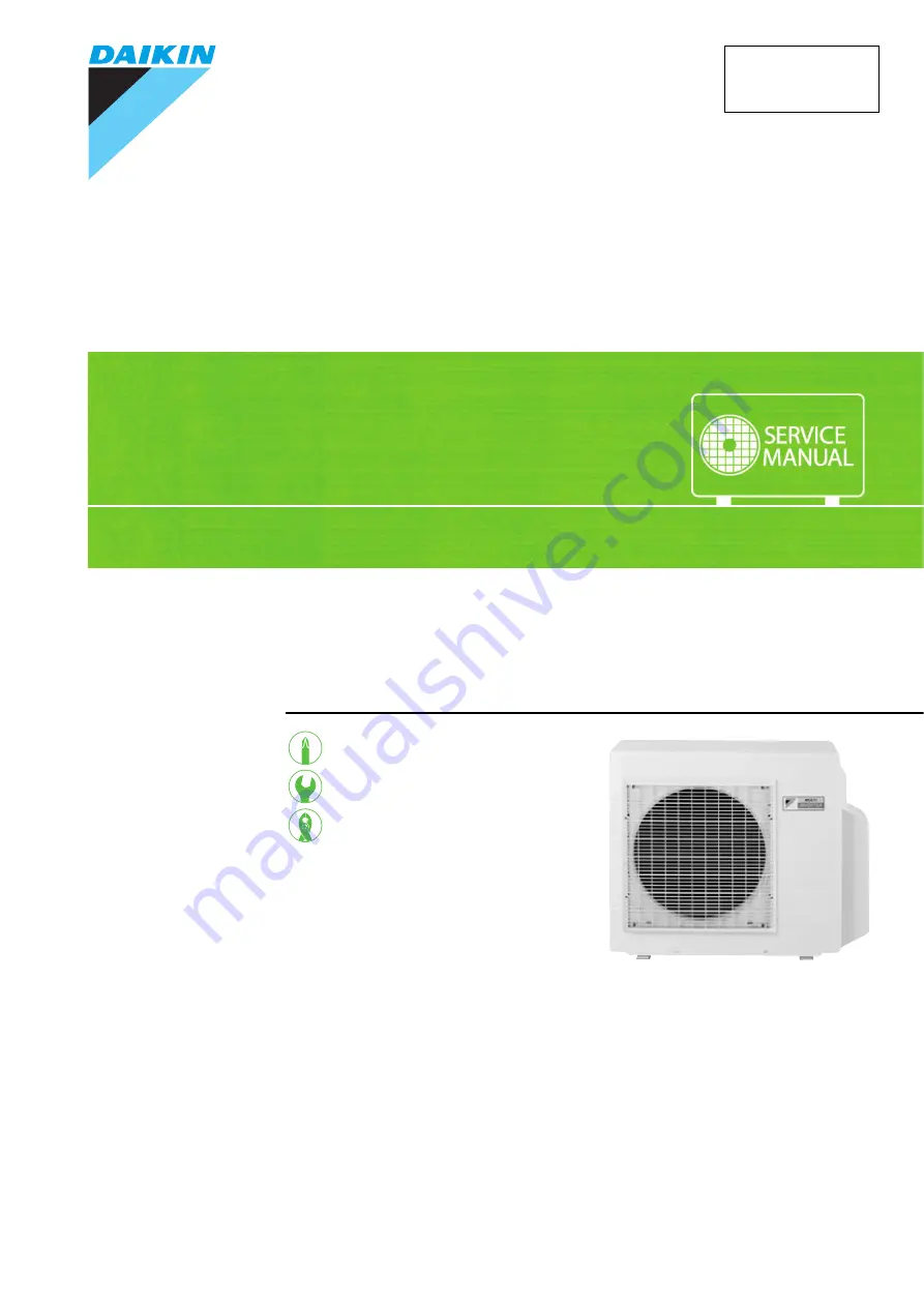
S E R V I C E M A N U A L
4.0/5.0/5.2/5.8/6.8 kW Class
Outdoor Unit
Inverter
Multi Type
Si121291EC
Страница 1: ...REMOVAL PROCEDURE S E R V I C E M A N U A L 4 0 5 0 5 2 5 8 6 8 kW Class Outdoor Unit Inverter Multi Type Si121291EC...
Страница 2: ...e Outdoor Unit zCooling Only zHeat Pump 3MKS50ESG 3AMX52E4V1B 3MKS50FSG 3MXS40K3V1B 3MKS58KVM 3MXS52E4V1B 3MKS58LVMA 3MXS52KVM 3MKS58LVMA9 3MXS52LVMA 3MKS68LVMA 3MXS52LVMA9 3MKS68LVMA9 3MXS68G3V1B 3MX...
Страница 3: ...lectrical Box 4 3 PCBs 9 4 Fan Motor 12 5 Sound Blankets 13 6 Coils Thermistors 16 7 Distributor 18 8 Four Way Valve 19 9 Compressor 20 Note The illustrations may be slightly different depending on th...
Страница 4: ...cedure Points 1 Remove the 4 screws and remove the top panel The illustrations are for 3 room models as representative 2 Remove the 6 screws of the front panel 3 Remove the screw of the shield plate 4...
Страница 5: ...ews and remove the discharge grille 7 8 Remove the 2 screws of the stop valve cover Slide the stop valve cover downward and remove it When reassembling make sure to fit the 5 hooks Step Procedure Poin...
Страница 6: ...ixing tape 2 Unfasten the 4 hooks and remove the electrical box cover 3 Detach the clamp and disconnect the connector S70 S70 fan motor When reassembling insert the clamp into either hole as below Som...
Страница 7: ...When reassembling insert the clamp of the electronic expansion valve coil ASSY into either hole as below 6 Pull out the clamp 7 Disconnect the connector S40 S40 overload protector 8 Pull out the clam...
Страница 8: ...XS52KVM 3MXS52LVMA 9 40 68 class 3AMX52E4V1B 3MX52E4V1B 11 Disconnect the connector S80 S80 four way valve coil The cooling only models have no harness for S80 12 Pull out the clamp of the thermistor...
Страница 9: ...the screws on the terminal board and disconnect all the connecting wires and the power supply wire 3 Remove the 2 screws and remove the wire fixture 4 Detach the outdoor temperature thermistor 5 Remov...
Страница 10: ...Electrical Box Si121291EC 8 Removal Procedure 6 Remove the screw of the electrical box 7 Lift up and remove the electrical box Step Procedure Points R17760...
Страница 11: ...ng work Step Procedure Points 1 Remove the service monitor PCB 1 Disconnect the connectors S52 S102 from the service monitor PCB 2 Unfasten the upper hook and remove the service monitor PCB 2 Remove t...
Страница 12: ...ransmission 3 Disconnect the 2 connectors for the reactor on the left side 4 Remove the 3 screws of the main PCB 5 Release the 4 hooks and lift up the main PCB 6 Release the relay harness for the comp...
Страница 13: ...The main PCB and the radiation fin are adhered to one another 8 Remove the 2 screws and remove the radiation fin When reassembling make sure to use the silicon grease 9 Remove the 3 screws and remove...
Страница 14: ...move the outdoor fan Nut size M6 When reassembling align the mark of the outdoor fan with the D cut section of the motor shaft When reassembling put the fan motor lead wire through the back of the fan...
Страница 15: ...er supplies before disassembling work Step Procedure Points 1 Remove the right side panel 1 Remove the 3 screws of the right side panel 2 Remove the 2 screws on the back 3 Remove the protection rubber...
Страница 16: ...Remove the 2 screws of the partition plate 2 Detach the clamp of the relay harness for the compressor 3 Lift up and remove the partition plate When reassembling make sure to fit the lower hook of the...
Страница 17: ...he shape of the sound blankets differs depending on the model 1 Remove the sound blanket top upper 2 Remove the sound blanket top inner 3 Open the sound blanket outer and pull it out 4 Open the sound...
Страница 18: ...rocedure Points 1 Pull out the electronic expansion valve coils 2 Remove the screw and remove the four way valve coil The cooling only models have no four way valve coil 3 Open the putty and remove th...
Страница 19: ...he edge of the thermistor and the fixture 5 6 Cut the clamp Pull out the outdoor heat exchanger thermistor 7 Remove the discharge pipe thermistor 8 Remove the assembly of thermistors Step Procedure Po...
Страница 20: ...gerant gas is empty in the circuit Be sure to apply nitrogen replacement when heating up the brazed part Do not use a metal saw for cutting pipes by all means because the sawdust comes into the circui...
Страница 21: ...four way valve with wet cloth and provide water so that the cloth does not dry Note Before working make sure that the refrigerant gas is empty in the circuit Be sure to apply nitrogen replacement whe...
Страница 22: ...g by non oxidation brazing Note Before working make sure that the refrigerant gas is empty in the circuit Be sure to apply nitrogen replacement when heating up the brazed part Do not use a metal saw f...
Страница 23: ...the overload protector Remove the protection bushing 5 Remove the putty 6 Remove the 2 nuts 7 Heat up the brazed parts 8 Remove the compressor Step Procedure Points R12916 Overload protector Protecti...
Страница 24: ...contents 09 2012 Si121291 First edition 02 2013 Si121291_A Model addition 3AMX52E4V1B 3MXS40K3V1B 3MXS52E4V1B 3MXS68G3V1B 4MXS68F3V1B 08 2014 Si121291EB Model addition 3MKS58 68LVMA9 3MXS52 68LVMA9 0...
Страница 25: ...ries supplied or specified by Daikin Ask a qualified installer or contractor to install those parts and accessories Use of unauthorised parts and accessories or improper installation of parts and acce...