background image

4-15

Chapter 4 

              Connection

W

IRING


OF

 V

OLTAGE

 D

ETECTION

 C

ABLE


AT

 B

ASE

 M

ETAL

 S

IDE

C

ONNECTION

C

HAPTER


4

4.6 Wiring of Voltage Detection Cable at Base Metal Side

When the extension cable is 30 m or more in length in total, use of the voltage detection cable at the base 
metal side is recommended.
The voltage detection cable needs to be wired so that the correct feedback of the arc voltage can be 
obtained. Connect the voltage detection cable as near as possible to the base metal to avoid detection of 
voltage decrease.
Use the voltage detection cable at base metal (optionally available: K5416N00 or K5416G00) by 
connecting with the wire feeder or to the voltage direct detection terminal at the base metal side on the 
front of welding power source.
When using the voltage detection cable, set the internal function F38 to "ON". (

6.7.1

-

 Setting 

procedure)
Details on the internal function F38 (

6.7.2.23

-

 F38: Arc voltage direct detection switching)

4.6.1 Wiring to wire feeder

This section explains how to connect the voltage detection cable at the base metal side to the wire feeder.

1.

Check that input power is turned off with the disconnect switch connected to the welding power 
source.

2.

Remove the right side panel of the wire feeder.

3.

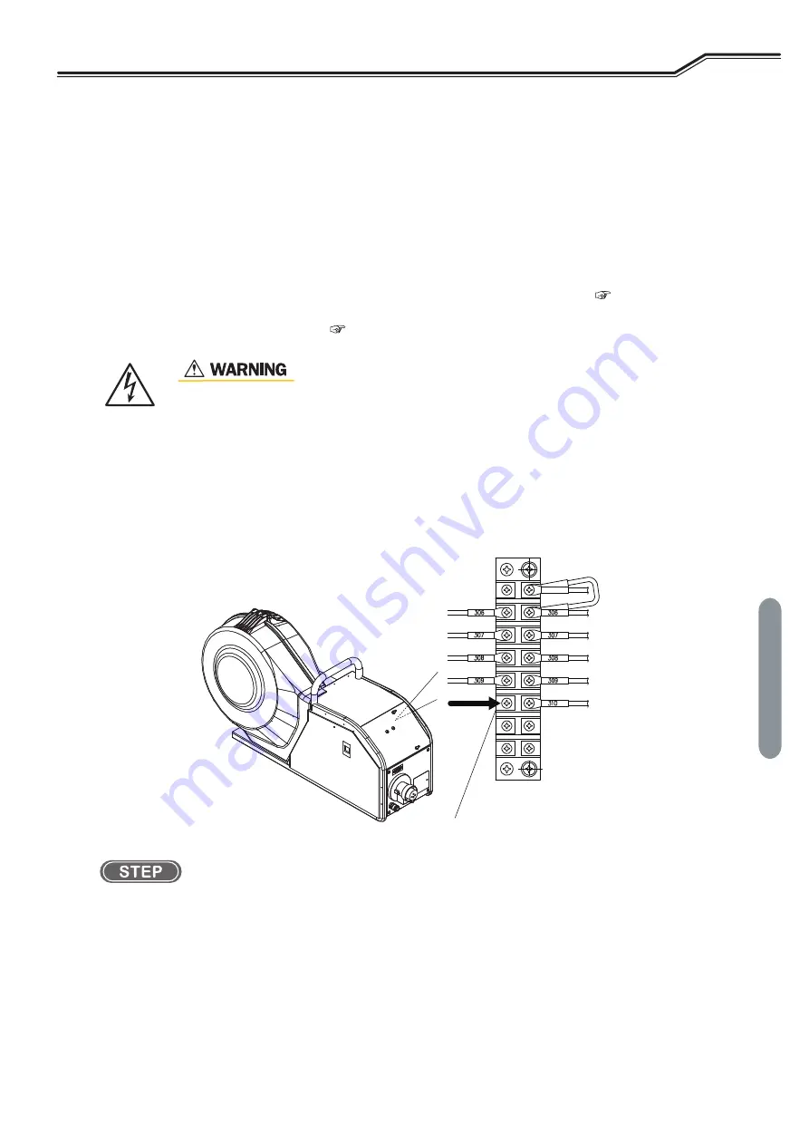
Connect the voltage detection cable at the base metal side to the terminal board in the wire feeder 
(wire No. 310).

Use the voltage detection cable at the base metal side via the blind bush with film.

 • Ensure to start the operation only after shutting off the input power by the contactor of 

the power distribution box connecting the welding power source. Otherwise, electric 
shock may occur. 

Terminal block

Wire feeder

Connection part of voltage detection cable

Содержание OTC Welbee WB-P320E

Страница 1: ...ad this instruction manual thoroughly for safe and proper use of the product August 2015 Manual No P30199 1 Model WB P320E Welbee Inverter P320E OWNER S MANUAL Pulsed MAG MIG Welding power source DAIHEN Corporation ...

Страница 2: ......

Страница 3: ...anual hereafter referred to as this manual explains the following points for safe use of the product Caution regarding the product Welding operation setting method Daily maintenance cleaning inspection Troubleshooting Store this manual in a safe place so that it can be referred whenever necessary ...

Страница 4: ...sure that installation operation maintenance of the welding power source and welding machine is performed by qualified personnel with sufficient knowledge and skills If this manual is lost or damaged immediately contact your dealer Copyright This manual is copyrighted and all rights are reserved by OTC Any part of the manual shall not be copied photocopied or reproduced without the prior consent o...

Страница 5: ...odel manufacture year serial number and software version number Refer to the diagram below for product information Attachment location and content of nameplate may vary depending on the purchased product Example Attachment location of the nameplate No Serial No 1 Same number as the nameplate in the rear X X 2 Product model Manufacture year Serial number XX X X year X X 3 Software version number X ...

Страница 6: ... 3 5 3 3 1 Transportation with lifting lug 3 6 CHAPTER 4 CONNECTION 4 1 Precautions for Connection Procedure and Grounding 4 1 4 2 Connecting the Welding Power Source 4 2 4 2 1 Connection of cable at output side 4 3 4 2 2 Connection of wire feeder 4 4 4 2 3 Connection of welding torch 4 5 4 2 4 Connection at TIG welding optional 4 6 4 2 5 Connection at DC STICK welding optional 4 7 4 2 6 Connectio...

Страница 7: ...lding result control function 7 4 7 2 2 Details of welding control items 7 5 7 3 Data Backup Utilization of data 7 10 7 3 1 Setting of welding conditions internal functions 7 11 7 3 2 Simplified data log function 7 13 7 3 3 Failure log function 7 14 7 3 4 Welding Result Control Function 7 14 7 3 5 Backup operation 7 14 7 3 6 Importing backup data 7 16 7 4 Initializing Welding Conditions and Intern...

Страница 8: ...TABLE OF CONTENTS vi MEMO ...

Страница 9: ...rstand the content before beginning operation The below symbols are categorized by the degree of possible hazard and damage The below symbols are categorized according to the content to be followed 1 2 Safety Precaution This section explains the safety precautions regarding operation of the welding power source Symbols Explanation Gives information regarding possible personal injury or loss of lif...

Страница 10: ...e or work areas Only authorized personnel or person with full understanding and experience of the welding power source must perform installation maintenance and repair of welding power source Make sure to attach a safety belt when working at high locations For those with pacemaker avoid being close to the machine during operation or work area until obtaining physician s approval Machine at operati...

Страница 11: ...source and wait three minutes or more The capacitors may be still charged even after the input power is cut Make sure that there is no charged voltage before starting the work Wear dry insulating gloves for protection Do not use damaged or wet gloves Tighten all cable connections and insulate them Do not wrap cables around the body Perform periodical maintenance and repair damaged parts if any bef...

Страница 12: ... For preventive measure from falling due to anoxia apply lifelines such as a safety belt For the welding operation in a narrow space perform the operation with the trained supervisor Periodically inspect the ventilation equipment to ensure correct and proper performance of ventilation To reduce the dust concentration install a partial exhaust facility such as fume suction device or install the col...

Страница 13: ... on gas pipe and closed containers such as tanks or drums Performing arc welding on flammable object such as fuel tank may cause explosion Furthermore welding on closed container such as tanks and pipes may cause burst Watch for fire and keep a fire extinguisher near the welding area Periodically blow the parts of welding power source with dry compressed air to remove dust Powder dust accumulating...

Страница 14: ...way from the gas discharge port Keep protective cap in place over valve except when gas cylinder is in use or connected for use Do not place the gas cylinder under high temperature Protect compressed gas cylinders from excessive heat mechanical shock and arcs Do not set welding torch to the cylinder or touch the cylinder with welding electrode For the gas regulator make sure to use a device for co...

Страница 15: ...ng by customer is out of the warranty scope When welding or watching a welder work wear face shield with a proper shade of filter See ANSI Z 49 1 listed in PRINCIPAL SAFETY STANDARDS to protect the face and eyes Wear safety goggles in the work area and the surrounding Ignoring the above may cause injury in the eye or burn from spatter and spattering dross Wear protective equipment such as protecti...

Страница 16: ... Electrical Code NFPA Standard 70 from National Fire Protection Association Safe Handling of Compressed Gases in Cylinders CGA Pamphlet P 1 from Compressed Gas Association Code for Safety in Welding and Cutting CSA Standard W117 2 from Canadian Standards Association Standards Sales Safe Practices For Occupation And Educational Eye And Face Protection ANSI Standard Z87 1 from American National Stan...

Страница 17: ...hase Three phase Rated frequency 50 60 Hz Rated input voltage 400 V Input voltage range 400 V 15 Rated input 15 2kVA 13 5kW Rated input current 21 8 A Rated output current 320 A Rated load voltage 30 V Rated output current range 30 to 320 A Rated output voltage range 12 to 34 V Maximum no load voltage 80 V Rated duty cycle DC 60 Pulse 60 Number of welding condition 100 Operating temperature range ...

Страница 18: ...tment may not meet the appropriate condition if a mixing gas other than those with the following mixing ratios is used MAG 20 CO2 Argon Ar 80 Carbon dioxide CO2 20 MIG 2 5 CO2 Argon Ar 97 5 Carbon oxygen CO2 2 5 MIG Ar Argon Ar 100 2 Available for applications either of STANDARD or HIGH 3 For STANDARD mode the standard mode or extended cable mode extended mode of power cable is available 6 7 2 1 F...

Страница 19: ...Ni Ferr 0 8 1 0 1 2 2 MIG 2 5 CO2 CrNi 0 8 1 0 1 2 2 CrNi Ferr 0 8 1 0 1 2 2 MIG 100 Ar Al 99 1 2 1 6 2 Al Mg 1 0 1 2 1 6 2 OP STICK DC TIG DC STICK 1 Note that the collective voltage adjustment may not meet the appropriate condition if a mixing gas other than those with the following mixing ratios is used CO2 Carbon dioxide CO2 100 MAG 20 CO2 Argon Ar 80 Carbon dioxide CO2 20 MAG 10 CO2 Argon Ar ...

Страница 20: ...SPECIFICATION PRODUCT SPECIFICATION AND CONFIGURATION CHAPTER 2 2 4 2 1 3 External dimensions This section explains the external dimensions of the welding power source 592mm 395mm 710mm ...

Страница 21: ...and radiation fin of the diode If dust and dirt accumulate on the radiation fin it may not only reduce the duty cycle but also result in degradation or burnout of the welding power source Rated duty cycle of this welding power source is 60 at the output of 320A 30V Rated duty cycle of 60 means the power source must be rested for 4 minutes after 6 minutes of continuous welding at the rated current ...

Страница 22: ...1 Optional accessories Remarks 1 Gas regulator To be prepared by the customer 2 2 3 Accessory not supplied 2 Wire feeder 3 Welding torch 4 Gas hose 3 m 2 5 Control cable for wire feeder 1 5 m 2 6 Power cable for torch side 2 m 2 7 Power cable for base metal side 2 m 2 8 Shielding gas To be prepared by the customer 2 2 3 Accessory not supplied 9 Digital remote control optional 2 2 4 Optional access...

Страница 23: ... 2 3 Accessory not supplied 2 Welding torch 3 Gas hose 3 m 2 4 Power cable for base metal side 2 m 2 5 Shielding gas To be prepared by the customer 2 2 3 Accessory not supplied 6 Digital remote control optional 2 7 Analog remote control 3 m optional 2 1 Standard component with welding power source Supplied when placing order for the welding power source 2 Optional extension cable and hose 5 m 10 m...

Страница 24: ...en opening the package 2 2 3 Accessory not supplied This section explains the accessories to be prepared by the customer before operating the welding power source Prepare the following No Name Suppliedunit 1 Optional accessories Remarks 1 Welding electrode holder To be prepared by the customer 2 2 3 Accessory not supplied 2 Power cable 38mm2 or more 2 3 Power cable for base metal side 2 m 2 4 Digi...

Страница 25: ...y available including remote control and voltage detection cable Name Remarks CO2 gas Carbon dioxide CO2 100 MAG gas Argon Ar 80 Carbon dioxide CO2 20 Argon Ar 90 Carbon dioxide CO2 10 MIG gas Argon Ar 97 5 Carbon oxygen CO2 2 5 MIG gas stainless Argon Ar 98 Oxygen O2 2 MIG gas stainless Argon Ar 97 5 Carbon oxygen CO2 2 5 MIG gas aluminum aluminum bronze Silicon bronze Argon Ar 100 Product name P...

Страница 26: ...xtension cable may cause an unstable arc Use extension cables with suitable length Unnecessarily long extension cable may cause an unstable arc No Product name Model 5 m 10 m 15 m 20 m 1 Gas hose BKGG 0605 BKGG 0610 BKGG 0615 BKGG 0620 2 Control cable for wire feeder BKCPJ 1005 BKCPJ 1010 BKCPJ 1015 BKCPJ 1020 3 Power cable torch side BKPDT 6007 BKPDT 6012 BKPDT 8017 BKPDT 8022 4 Power cable base ...

Страница 27: ...tion of the welding power source Socket for wire feeder Socket for analog remote control Output terminal Torch side Output terminal Base metal side Power switch Main power lamp Operation panel ޓޓ 6 2 Function on Operation Panel Terminal for directly detecting voltage on the base metal side Input cable Grounding cable Blind bush for drawing externally connecting wire Cover for external connections ...

Страница 28: ...PART NAMES PRODUCT SPECIFICATION AND CONFIGURATION CHAPTER 2 2 12 ...

Страница 29: ...peration Setting to an extremely high output voltage may result in damage to the welding power source When the welding power source is used in a humid environment such as construction site or location with highly conducting material such as steel plate or on steel structure install a leakage breaker Otherwise electric shock due to leakage of electricity may occur Be sure to install a switch with f...

Страница 30: ...ment and partial exhaust facility in welding work area 3 1 2 1 Ventilation equipment When welding is required in tank boiler reaction tower or hold of a ship closed space or any other places of poor ventilation ensure to provide ventilation equipment Condition of ventilation equipment Oxygen concentration of 18 or more must be maintained in the welding work area 3 1 2 2 Partial exhaust facility To...

Страница 31: ... 20 C Location with an altitude of less than 1000 m Location with an incline of 10 or less Location with no metallic foreign body such as spatter entering the welding power source Installation distance of 30 cm or more between the welding power source and the wall or other welding power source Ensure not to block the ventilation hole Location with no wind on the arc section Install a wind shield t...

Страница 32: ...elding power source Welding cables Do not use an unnecessarily long cable Place a base metal cable and a torch side cable as closely as possible Equipotential bonding Bonding of all metallic objects in the surrounding area should be considered Earthing of the workpiece The connection of the workpiece to earth should be made by a direct connection to the workpiece but in some countries where direct...

Страница 33: ...and floor Do not apply strong shock to the welding power source when placing it on the floor It may cause damage to the welding power source Since large current abruptly flows inside the welding power source during welding other machine near the welding power source may be failed due to electromagnetic noise Follow the instructions below Do not ground the welding power source commonly with other m...

Страница 34: ...dents be sure to observe the following For operation of a crane or hoisting make sure that a qualified personnel operate them with attention to the surrounding area for safety Use the lifting tool such as wire and shackle suitable for the weight of the welding power source Hoist according to the specified procedure Lift the welding power source alone with two wires using all of the eye bolts Do no...

Страница 35: ...l parts of the welding power source Have a qualified electrical engineer ground the case of the welding power source and base metal or jig electrically connected in accordance with local regulation Make sure to cut the input power with the disconnect switch in the box connected to the welding power source Do not turn on the input power before confirming the completion of connection Use a cable wit...

Страница 36: ...source until confirming the completion of connection work Otherwise electric shock may occur Connection of cable at output side 4 2 1 Connection of cable at output side Connection of wire feeder 4 2 2 Connection of wire feeder Connection of welding torch 4 2 3 Connection of welding torch Connection of shielding gas 4 2 6 Connection of shielding gas Connection of input power connectors 4 3 Groundin...

Страница 37: ...tighten them in the clockwise direction 2 Connect the power cable for torch side to the output terminal torch side Connect the connectors as same as above Connection for cable at output side is complete Procedure is followed by 4 2 2 Connection of wire feeder Use a grounding cable for the case of welding power source and perform grounding Otherwise voltage may increase in the case or base metal wh...

Страница 38: ...rol cable 10 cores to the socket for the wire feeder Fit the concave part of the connector and convex part of the socket for secure connection and tighten the knurled screws in the clockwise direction When using an analog remote control optional accessory remove the cap of socket for analog remote control and insert the control cable 6 cores Connection for wire feeder is complete Procedure is foll...

Страница 39: ...n using the water cooled welding torch connect the water feeding hose and condensing hose of the welding torch to the wire feeder Fully insert the hose end to the connection port of wire feeder For disconnection hold the hose end and press the collar part to the arrow mark direction shown in the figure Connection for welding torch is complete Wire feeder When air cooled welding torch is used When ...

Страница 40: ...terminal torch side and base metal Connect the connectors as same as above In using the welding power source for TIG welding prepare a welding torch by the customer Contrary to the normal connection the TIG welding requires connection of the welding torch to the output terminal base metal side Also connect the power cable for base metal side to the output terminal torch side After five seconds hav...

Страница 41: ... for secure connection and tighten them in the clockwise direction 2 Connect the cable for welding electrode holder side to the output terminal torch side Connect the connectors as same as above In using the welding power source for DC STICK welding prepare a welding electrode holder by the customer After five seconds have passed the safety voltage approx 15 V is automatically provided Power cable...

Страница 42: ... sure to observe the following points to prevent from suffocation due to gas leakage or explosion Be sure to turn off the shielding gas at the main tap when the welding power source is not in use Securely connect the gas hose and attach the gas regulator with a wrench so that there is no gas leakage For the gas regulator make sure to use a device for compressed gas cylinder that conforms to the sp...

Страница 43: ...ation with highly conducting material such as steel plate or on steel structure install a leakage breaker Otherwise electric shock due to leakage of electricity may occur Be sure to install a switch with fuse or a circuit breaker for motor to the input side of each welding power source Otherwise electric shock and fire due to overcurrent or damage to the welding power source may occur If the weldi...

Страница 44: ...are appropriate 3 1 1 Welding power source equipment Perform grounding for the case of the welding power source Ground terminal is properly grounded when grounding cable of the welding power source is connected to the breaker s ground terminal No tools or equipments are left placed on the surface of the welding power source Do not place any material on the surface of the welding power source 4 5 C...

Страница 45: ...rol cable for wire feeder BKCPJ 1010 10 m For details on cables see 2 2 4 2 Details on extension cables and hoses 7 Cable at torch side BKPDT 6012 10 m 8 Cable at base metal side BKPDT 6012 10 m 9 Gas hose BKGG 0610 10 m 10 Gas regulator To be prepared by the customer 11 Conduit Z318P50 Guide adaptor attachment part 9 16 18UNF When using the conduit 7 16 20UNF guide adaptor L7810D04 is also requir...

Страница 46: ...tops output of the welding power source When combining switches use a push lock turn reset switch for preventing accidental reset 5 9 IN EXT1 External input 1 Reserve inputs for expanding terminal functions Setting the internal functions Function allows you to externally open and close the gas valve and perform inching operation 6 7 Setting Internal Functions 6 9 IN EXT2 External input 2 7 9 IN EX...

Страница 47: ...o prevent electric shock ensure to follow the instructions below Wiring should be performed by qualified persons or persons familiar with the welding machine Do not touch the input and output terminals and the internal live electrical parts of the welding power source Before starting the work make sure to cut the input power with the disconnect switch connected to the welding power source and wait...

Страница 48: ... mm from the end while pressing the button on the terminal block and insert the cable 5 Check the wiring and place the cover for external connection back to the welding power source The control cable drawn out from the terminal for external connection should be kept away from the welding power cable or the torch cable as much as possible Otherwise failure may occur due to noise during use Do not p...

Страница 49: ...urce When using the voltage detection cable set the internal function F38 to ON 6 7 1 Setting procedure Details on the internal function F38 6 7 2 23 F38 Arc voltage direct detection switching 4 6 1 Wiring to wire feeder This section explains how to connect the voltage detection cable at the base metal side to the wire feeder 1 Check that input power is turned off with the disconnect switch connec...

Страница 50: ...cable at the base metal side to the voltage direct detection terminal at the base metal side of the welding power source 1 Check that input power is turned off with the disconnect switch connected to the welding power source 2 Connect the voltage detection cable at the base metal side to the voltage direct detection terminal at the base metal side Wiring of voltage detection cable is complete Weld...

Страница 51: ...d with a power feeding brush to the positioner Insulate the power feeding brush from the jig base and connect the voltage detection cable base metal side to the jig base TIPS Before wiring the voltage detection cable check that conduction between the jig base and the base metal is stable Power cable at the base metal side Voltage detection cable at the base metal side Stage 1 Stage 2 Stage 3 Conne...

Страница 52: ...WIRING OF VOLTAGE DETECTION CABLE AT BASE METAL SIDE CONNECTION CHAPTER 4 4 18 ...

Страница 53: ...tilation equipment does not give sufficient performance ensure to use respiratory protective equipment For preventive measure from falling due to anoxia apply lifelines such as a safety belt For the welding operation in a narrow space perform the operation with the trained supervisor Periodically inspect the ventilation equipment to ensure correct and proper performance of ventilation To reduce th...

Страница 54: ... from spatter and spattering dross Wear protective equipment such as protective leather gloves long sleeve clothes leg covers and leather apron Ignoring the above may cause electrical shock and burn Install protective screens or barriers to protect the eyes of others in the work area from arc ray Wear an ear protector when noise level is high Ignoring the above may cause hearing disorder When the ...

Страница 55: ...gas should be adequate Ensure the adequate shielding gas flow rate as follows CO2 MAG gas MIG gas 10 to 25L min 15 to 25L min 11 When the shielding gas is mixed each gas pressure should be the same Set pressures of the respective gas to the same level 12 Oil or other dirt should not be adhered on the welding wire Consider a measure to wipe off the dirt 13 In the CO2 and MAG welding the particle di...

Страница 56: ... torch cable has no bending at a sharp angle If the liner is clogged with dirt or when inched wire has flaw replace the liner with a new one In replacing the liner follow the precautions on the attached manual of welding torch for appropriate handling In cutting the liner take care for the followings If the liner is too long feeding resistance increases resulting in shorter life of wire feeder If ...

Страница 57: ...en the main tap of shielding gas When the gas regulator is equipped with a pressure gauge open the main tap by checking the pressure gauge until the appropriate pressure is obtained Handle the gas cylinder according to the related laws or regulations as well as the internal standard of the customer Note that the gas cylinder contains a high pressure gas Wrong operation may cause gas explosion resu...

Страница 58: ...ximately 10 mm Releasing the WIRE INCH key will stop the wire feeding For excessive wire cut the wire using a plier Turning the parameter adjusting knob during the wire feeding can adjust the feed speed TIPS Wire feeding is also enabled by a remote control optional Turning the welding current adjustment knob can adjust the feed speed 6 8 Operation of Analog Remote Control Optional Do not look into...

Страница 59: ...tal change of the welding conditions the erroneous operation prevention function is equipped for the operations other than inching gas check or reading saving of the welding condition In using the analog remote control however the adjustment of current voltage by the analog remote control is available The erroneous operation prevention function does not need any password to release the lock To all...

Страница 60: ...metal In DC STICK welding arc start requires setting of the welding electrode in the electrode holder and contact of the electrode with the base metal 2 A series of welding operation is completed by the torch switch operation 6 6 3 Crater setting At the end of welding the average value of the welding current and the welding voltage at the last second of the welding sequence is displayed on each di...

Страница 61: ...f press the CURRENT SETTING DISPLAY SWITCH key to light up the LED In the adjustment by the remote control this operation is not necessary Turn the parameter adjustment knob for the remote control the welding current adjustment knob to adjust the welding current 3 Adjust the welding voltage When the LED of the VOLTAGE SETTING DISPLAY SWITCH key is off press the VOLTAGE SETTING DISPLAY SWITCH key t...

Страница 62: ...welding end This section explains the supply stop procedure of power shielding gas after the welding end 1 Close the main tap of the shielding gas 2 Press the GAS CHECK key The LED of the GAS CHECK key lights up and the shielding gas remained in the gas piping is discharged 3 After the shielding gas is discharged press the GAS CHECK key The LED of the GAS CHECK key lights off to stop gas check 4 S...

Страница 63: ... end of welding Voltage INDIVIDUAL 10 0 to 45 0 V 23 5 V Voltage SYNERGY 100 to 100 0 Post flow time 0 to 10 sec 0 4 sec Set the gas discharge time after the welding ends Arc spot time 0 1 to 10 sec 3 sec Set the welding time at arc spot Arc characteristics 10 to 10 0 Set the arc to the condition from soft to hard Welding condition memory No 1 to 100 1 Register the welding conditions storable up t...

Страница 64: ...e display time for the current voltage after completion of welding F9 Analog remote control scale 200 350 350 A Configures the settings of scale plate of the analog remote control F10 Motor over current detection level 20 to 150 70 Sets the over current warning level for the rated current of the wire feed motor F11 Fine adjustment of welding conditions memory OFF 1 to 30 OFF Allows fine tuning the...

Страница 65: ...ng 0 to 9 0 Sets the functions of input terminal of the programmable I O F30 External input 2 setting 0 F31 External input 3 setting 0 F32 External input 4 setting 0 F33 No function OFF fixed OFF No functions are provided F34 F35 F36 F37 F38 Arc voltage direct detection switching OFF ON OFF Sets the voltage direct detecting terminal on the base metal side of the welding power source and voltage de...

Страница 66: ...OFF not to use torch switch ON uses the torch switch F52 Data type of data log function 0 to 8 0 Sets sample data on the data log 0 No sampling 1 Welding current Welding voltage Sequence information 2 Current command Voltage command Feeding command 3 Current command Welding current Welding voltage 4 Current command Welding current Sequence information 5 Welding current Voltage command Welding volt...

Страница 67: ...on and crater condition in the percentage based on the current value of the welding condition OFF invalid ON settable with percentage F68 Setting of current value initial condition 10 to 300 100 Sets the current value of the initial condition in the percentage based on the current value of the welding condition F69 Setting of current value crater condition 10 to 300 100 Sets the current value of t...

Страница 68: ...ps the discharge Pressing this key again lights off the LED stopping the shielding gas discharge 9 WIRE INCH key Feeds the wire 5 4 Wire Inching The LED lights during when the key is pressing allowing the wire to be fed The feeding speed can be adjusted by the parameter adjustment knob When the analog remote control optional is connected the speed can be adjusted by the welding current setting kno...

Страница 69: ...adjust the wave frequency by the parameter adjustment knob The set wave frequency is displayed on the left digital meter 21 TORCH key Select air cooled welding torch or water cooled welding torch to be used Switching the mode is enabled by pressing the key When the LED is ON water cooled welding torch mode When the LED is OFF air cooled welding torch mode 22 VOLT ADJUST key Sets welding voltage Sw...

Страница 70: ...voltage shielding gas type and wire type wire diameter currently set and reads them out for use Synergic adjustment of voltage 6 2 Function on Operation Panel Using the VOLT ADJUST key enables to automatically set the welding voltage according to the welding current Fine adjustment of the welding voltage automatically set is also available Penetration control 6 6 7 Penetration control adjustment U...

Страница 71: ...lding mode setting Setting crater treatment 6 6 3 Crater setting Setting pre flow Setting gas discharge time 6 6 2 Setting welding parameter Setting initial condition Setting welding current voltage 6 6 2 Setting welding parameter Setting welding condition Setting welding current voltage 6 6 2 Setting welding parameter Setting crater condition Setting welding current voltage 6 6 2 Setting welding ...

Страница 72: ...hen the analog remote control is connected to the machine even if the stored welding condition is read the set values of the analog remote control apply to the welding current and welding voltage of welding condition TIPS Use of the internal function F44 enables to read out the registered welding condition by the analog remote control optional 6 7 Setting Internal Functions Use of the internal fun...

Страница 73: ...etting value of the welding current registered to the JOB No if any is displayed if there is no registration is displayed and the A LED lights up When there is no registration data on the selected JOB No is displayed on the left digital meter When there is any registration data on the selected JOB No the setting value of the welding current is displayed on the left digital meter At this time the L...

Страница 74: ...ital meter in a flashing mode and the LED of JOB No lights up On the left digital meter the setting value of the welding current registered to the JOB No if any is displayed if there is no registration is displayed and the A LED lights up When there is no registration data on the selected JOB No is displayed on the left digital meter When there is any registration data on the selected JOB No the s...

Страница 75: ...ayed on the right digital meter in a flashing mode and the LED of JOB No lights up To delete all the registration at the same time turn the parameter adjustment knob counterclockwise to display ALL on the right digital meter When ALL is selected the current welding condition set on the operation panel is also deleted and the welding parameters including the internal functions return to the initial...

Страница 76: ... is displayed on the left right digital meters and turn off the power switch The power LED switch lights off The status returns to normal when the power switch is turned on The welding condition of the selected JOB No is deleted and End is displayed on the left right digital meters A V s 㸣 m min sec JOB No Hz ...

Страница 77: ...nt at aluminum welding Reference Aluminum material Wire diameter mmΦ Welding method Range of stable welding power source A HARD ALUMINUM A5183 A5336 etc 1 0 DC 60 to 150 DC PULSE DC WAVE PULSE 50 to 150 1 2 DC 75 to 250 DC PULSE DC WAVE PULSE 50 to 250 1 6 DC 100 to 320 DC PULSE DC WAVE PULSE 75 to 320 SOFT ALUMINUM A4043 etc 1 2 DC 90 to 250 DC PULSE DC WAVE PULSE 60 to 300 1 6 DC 100 to 320 DC P...

Страница 78: ...are set according to the welding sequence 6 6 2 1 Welding sequence The basic welding sequence is the process of PRE FLOW MAIN CONDITION and POST FLOW To this sequence initial condition and crater fill condition can be added depending on the crater setting The welding parameters such as gas discharge time welding current and voltage should be set to this sequence Each sequence process has the follo...

Страница 79: ... key m min On A Off and the value displayed on the left digital meter switches to the display of wire feed speed Pressing the CURRENT SETTING DISPLAY SWITCH key again to light on the LED of the key m min Off returns the display to the one of welding current 3 Set the welding voltage Check the lighting on the LED V unit of welding voltage When the LED is lights off press the VOLTAGE SETTING DISPLAY...

Страница 80: ...al condition Available Adding to the above the welding process is available by the initial condition before the main welding 6 6 3 3 Crater ON with initial condition CRATER FILL ON with pulse Unavailable After the main welding the welding process on the Crater condition with pulse is available 6 6 3 2 Crater ON no initial condition Available Adding to the above the welding process is available by ...

Страница 81: ... Select CRATER OFF by the CRATER FILL key In synchronous to the ON OFF operation of the torch switch the welding starts stops Torch switch Gas flow Output voltage Wire feeding speed Welding current Main welding Anti stick time ON OFF Pre flow Post flow No load voltage Slow down speed Welding current ON OFF ...

Страница 82: ... The torch switch should remain depressed and held during the CRATER phrases When selecting CRATER FILL ON no pulse Regardless of the setting by the WELDING METHOD key the machine automatically turns to the welding with no pulse when the crater fill process starts When selecting CRATER FILL ON with pulse When DC PULSE or DC WAVE PULSE is selected by the WELDING METHOD key the machine automatically...

Страница 83: ...witch should remain depressed and held during the INITIAL and CRATER phrases When selecting CRATER FILL ON no pulse Regardless of the setting by the WELDING METHOD key the machine automatically turns to the welding with no pulse when the crater fill process starts When selecting CRATER FILL ON with pulse When DC PULSE or DC WAVE PULSE is selected by the WELDING METHOD key the machine automatically...

Страница 84: ... on the nozzle for arc spot see the instruction manual of the torch 6 6 5 Welding voltage adjustment This section explains how to adjust the welding voltage The adjustment of welding voltage can be carried out either by the SYNERGIC mode or INDIVIDUAL mode TIPS Some conditions such as synergic condition does not meet the appropriate level if a mixing gas ratio of shielding gas is not the specified...

Страница 85: ...arc condition TIPS It is likely that good weld can be obtained by adjusting it to hard in low current region and soft in high current region When using an extended cable for the base material side torch side or using an extended torch cable it is likely that good welding can be performed by adjusting it to hard 6 6 7 Penetration control adjustment This section explains how to adjust the penetratio...

Страница 86: ... or more it disappears In this case the wire feeding speed becomes stable and only the unit pulse condition changes Image of welding bead form in the wave frequency TIPS This function is available when DC WAVE PULSE is selected by the WELDING METHOD key Wave pattern of the welding bead varies depending on the type of welding material travel speed and the heat input during welding The welding mater...

Страница 87: ...r the DISPLAY CHANGE key Adjustment of wave frequency is complete Press the DISPLAY CHANGE key and select either INITIAL CONDITION MAIN CONDITION or CRATER FILL CONDITION The LED for the selected welding sequence lights up The LED for the WAVE FRQ key lights up The wave frequency setting value appears on the left digital meter Adjust the value between 0 5 to 32 Hz Is IE I A m min V s A V s 㸣 Hz JO...

Страница 88: ...functions TIPS The internal function is activated at the point when the setting value is changed To change the set values of internal functions ensure that there is no mistake in the function No as well as in the function setting 1 Depress the F Function key for one second or more 2 Turn the parameter adjustment knob to display the function No to set 3 Press the F Function key again The display on...

Страница 89: ...or the length of extension cable longer than 30 m The LED of STANDARD starts flashing when setting to ON OFF Standard mode TIPS In using the welding power source in the HIGH mode the setting of this function is set to OFF and cannot be changed 6 7 2 2 F4 Auto Semi auto mode In combining the welding power source with a robot or an automatic machine set I O interface of the welding source according ...

Страница 90: ... is output even if the wire is not welded 2 If an external command voltage is input it should be input to the terminal pins 1 3 1 4 of the remote control receptacle as shown in the below figure Relationship between input and output is as the charts provided in F5 Maximum external command voltage 6 7 2 3 F5 Maximum external command voltage Ensure that the command voltage is input at least 100 ms be...

Страница 91: ...range of upslope time 0 0 to 10 0 sec 6 7 2 5 F7 Downslope time When the difference between the welding current and crater current is large the wire may plunge into weld pool at the change of the conditions the wire is fed by inertia because the speed reduction is too late In this case adjust the time period changing from the welding current to the crater current downslope time longer Setting rang...

Страница 92: ...output of the welding power source is not stopped According to the use environment such as wires and torches and the customer s judgment criteria adjust the detection level at your discretion 6 7 2 9 F11 Fine adjustment of welding conditions memory When the analog remote control optionally available is used fine adjustment of the welding current and welding voltage of welding condition stored on t...

Страница 93: ...cool the welding torch as the welding ends The operation time of water cooled pump at this time can be set Setting range of water cooled pump operation time 20 to 60 min ON Water cooled pump is always ON 6 7 2 11 F13 Turbo start The welding power source has the turbo start function using capacitor discharge in order to obtain smooth welding start ON enables the function OFF disables the function T...

Страница 94: ... voltage adjustment Set the anti stick time voltage which is the anti stick processing time and voltage Optimum setting of the anti stick time voltage enables to obtain the following effects At the welding completion wire adhesion to the base material can be prevented The shape of wire tip can be arranged to obtain a stable start of the next welding The time and voltage for anti stick process are ...

Страница 95: ...value an error code is displayed Set the value in the range of 260 to 400 V TIPS The factory default setting is 320 V However the specification of input voltage as welding power source is the range of 340 to 460 V If input voltage is lower than this range it may affect welding performance 6 7 2 17 F21 Maximum cooling fan operation The cooling fan can be rotated at the maximum rotation speed at all...

Страница 96: ...ed in the unit of 0 1 m min Switching to the welding current display can check the welding current value automatically set In using the welding power source in the automatic machine mode refer to the following diagram for the relationship of command voltage and the wire feed speed when the internal function F4 Auto Semi auto mode is used with the setting of Automatic machine 1 mode TIPS The wire f...

Страница 97: ...n terminal block 4 5 2 Connection of automatic machine The functions allocable to F29 to F32 are as follows Setting Function name Explanation 0 No function is allocated 1 Gas valve Causing short circuit between terminals opens the gas valve 1 2 Inching Causing short circuit between terminals starts inching 3 Retract When inching operation is performed after short circuit is caused between terminal...

Страница 98: ...ut the JOB No 3 Example 3 In reading out the welding condition of the JOB No 7 Setting F30 and F31 to 5 and turning the two signals of the external input terminal IN EXT2 IN EXT3 to ON enable to read out the JOB No 7 For F29 and F32 other functions can be set 5 Even after reading out the welding condition by this function welding method can be changed either via the front panel or by the DC PULSE ...

Страница 99: ...ifts to the registered JOB No The condition can not be changed during welding To release the JOB shift mode release the external input terminals The digital meter displays current and voltage after 2 sec have passed Secondary condition current ON OFF 1 Primary condition current 5 2 1 㩷 㩷 㩷 OPEN CLOSE OPEN OPEN CLOSE OPEN 㩷 䌉䌎 EXT3 䋨F31䋺䇸5䇹䋩 䌉䌎 EXT1 䋨F29䋺䇸5䇹䋩 JOB No Primary condition Secondary cond...

Страница 100: ...nt value The current value displayed on the digital meter is obtained by software processing of the average value of outputs therefore it may not be consistent with the value indicated on a needle meter etc When this happens using this function enables to finely adjust the current display value For F39 set gain and for F40 set offset Changing the set value only corrects the display the output weld...

Страница 101: ...ased on the center of welding voltage setting knob To increase the welding voltage turn the knob clockwise and to reduce the welding voltage turn the knob counterclockwise The fine adjustment range for welding voltage is up to 20 OFF disables the function In the following cases this function cannot be used Welding conditions are not registered to the memory Analog remote control optional is not co...

Страница 102: ...ternal function F45 is set to ON automatically the setting of No crater is selected disabling other welding modes The CRATER FILL key does not work Welding method at crater treatment is the same as that of main welding In the following cases this function cannot be used Internal function F11 Fine adjustment of welding conditions memory is set to 1 to 30 enabled Internal function F44 Reading weldin...

Страница 103: ... and doubleclicking Single clicking or double clicking operation should be within 0 3 seconds At the time of transition to crater press the torch switch for at least 0 3 seconds Welding method at crater treatment is the same as that of main welding Example In the setting examples of Crater setting ON Initial condition OFF Welding current 100 A Crater current 60 A F48 ON F49 10 and F50 20 the follo...

Страница 104: ... F51 Special crater repeat In the sequence of main welding of the CRATER FILL ON REPEATED during start input holding the torch switch operation can switch the welding and crater treatment repeatedly as many time as needed ON Setting of CRATER FILL ON REPEATED is applied and transits to the crater treatment by single clicking of the torch switch during the welding sequence start input holding It is...

Страница 105: ...rt or 5 Loading welding condition 6 7 2 33 F52 Data type of data log function This function enables to select data to save when using the data log function The patterns of data which can be saved are as shown in the below table For data log function 7 3 Data Backup Utilization of data Setting Welding current Welding current Welding voltage Welding voltage Wire feed speed Wire feed speed Command va...

Страница 106: ...ver in the pulse condition of the wave pulse welding at HIGH side fine adjustment is available to the standard pulse peak current at HIGH side by setting the adjustment value Example of current waveform of wave pulse welding 6 7 2 42 F65 Fine adjustment of L base current Set the adjustment value in the range of 150 to 150 A Fine adjustment of unit pulse condition The unit pulse conditions such as ...

Страница 107: ...alue Example of current waveform of wave pulse welding 6 7 2 42 F65 Fine adjustment of L base current Set the adjustment value in the range of 1 5 to 1 5 ms Fine adjustment of unit pulse condition 6 7 2 37 F60 Fine adjustment of pulse peak current Fine adjustment of unit pulse condition Example of current waveform of wave pulse welding 6 7 2 42 F65 Fine adjustment of L base current 6 7 2 39 F62 Fi...

Страница 108: ...le of current waveform of wave pulse welding 6 7 2 43 F66 Adjustment of feed amplitude ratio This function sets the feed amplitude ratio of wire amplitude change of wire feed speed in the wave pulse welding When the wave frequency is under 5 Hz the wire feed speed is adjusted By fine adjusting the amplitude of this feed speed optimized welding result for the specific purpose can be obtained Set th...

Страница 109: ...e of the initial condition can be set in percentage based on the current value of the welding condition Setting range of current value initial condition 10 to 300 6 7 2 46 F69 Setting of current value crater condition The current value of the crater condition can be set in percentage based on the current value of welding condition Setting range of current value crater condition 10 to 300 6 7 2 47 ...

Страница 110: ...ptimum welding voltage according to the welding current is automatically set and fine adjustment is available for the set welding voltage Align the welding voltage adjustment knob to the center mark and adjust the voltage with the position as the standard INDIVIDUAL adjustment The welding voltage can be individually adjusted without being influenced by the welding current 3 Inching button Feeds th...

Страница 111: ...ible if the erroneous operation prevention function is disabled NOTE Write down the password on a piece of paper and store it safely The current password will be requested also when you change it If a password is set and the erroneous operation prevention function is enabled the erroneous operation prevention function will not be disabled even if the power is turned off and on or if the welding co...

Страница 112: ...ction the password will be requested Hold the two keys pressed down until Loc is displayed on the left digital meter PAS Loc will be displayed in order Release the keys after Loc is displayed If a password has already been set Loc will flash To change the password delete the password with the operation from the step 2 of 7 1 2 Disabling erroneous operation prevention and go to the next step 7 1 2 ...

Страница 113: ...e digit specified as password 3 Select the tens place digit and ones place digit in the same manner as the step 2 4 Press the ENTER key Loc flashes on the left digital meter PAS Loc will be displayed in order The hundreds place flashes on the right digital meter Display the number specified as the password and press the DISPLAY CHANGE key Then the tens place will flash on the right digital meter W...

Страница 114: ...ire consumption used in welding kg P21 0 0 to 999 Target wire consumption kg P22 0 0 to 5 Operation at the time when the target wire consumption is achieved Total welding time P30 0 Cumulative total welding time minute P31 0 0 to 999 Target total welding time minute P32 0 0 to 5 Operation at the time when the target total welding time is achieved Welding monitor P40 0 Max fluctuation value of aver...

Страница 115: ...9 The count value will be cleared according to the P12 setting If continuous operation is enabled the value will be cleared when exceeding 999 and return to 0 P11 Target value of welding points Select the target value of welding points in the range from 0 to 999 When the P10 count value reaches the number of welding points specified here an alarm appears indicating that the target is achieved 7 2 ...

Страница 116: ...ed P21 Target wire consumption Select the target value of wire consumption in the range from 0 to 999 kg When the P20 count value reaches the wire consumption specified here an alarm appears indicating that the target is achieved 7 2 2 6 Alarm indication when target is achieved P22 Operation at the time when the target wire consumption is achieved Select the operation from 0 to 5 for the time when...

Страница 117: ...ding is monitored When it exceeds the range specified here an alarm displays and the output stops P40 Max fluctuation value of average range monitor If the average current voltage per second becomes out of the allowable tolerance range specified in P41 to P44 an alarm is displayed indicating the following 7 2 2 7 Alarm indication at the time of WARNING detection Welding Monitor P45 P46 P41 Current...

Страница 118: ... by the torch switch ON to the stop of output triggered by the torch switch OFF is counted and accumulated as welding time The setting range of count value is between 0 to 999 hours The time between 0 and 99 9 hours are displayed in the unit of 0 1 hour and the time exceeding 100 hours is displayed in the unit of 1 hour The count value of P51 will not be cleared according to the P32 setting Refer ...

Страница 119: ...shows a current error The control No P40 flashes on the left digital meter and the difference between the average value and specified value 30 on the right digital meter with the A LED lighting Example While welding is conducted with the welding current 200A Current tolerance 10 220A the average current during welding rose to 230A and the WARNING judgment time specified in P45 elapsed The right ex...

Страница 120: ... as FAT32 Compatibility of the following USB flash drives has been confirmed Model No SFU22048E3BF2SA W D0 111 STD swissbit Model No SFU22048E1BP2TO W D0 111 STD swissbit There is software allowing you to easily display waveforms and edit welding conditions You can download it from our home page URL http www daihen co jp products welder software en html No Data Backup Import 1 Welding Condition En...

Страница 121: ...rrent 1 A AD wld_feed Welding feed speed 0 1 m min E pre_vset Initial voltage 0 1 V AE cre_feed Crater feed speed 0 1 m min F pre_uni_vset Initial voltage synergic 1 AF ant_tim_adj Anti stick time adjustment 0 01 s G wld_iset Welding current 1 A AG ant_vset_adj Anti stick voltage adjustment 0 1 V H wld_vset Welding voltage 0 1 V AH sldwn_adj Slowdown adjustment 0 1 m min I wld_uni_vset Welding vol...

Страница 122: ... fine adjustment 1 A AS CreIsetPer reserved T pls_pkt_adj Pulse peak time fine adjustment 0 1 ms AT TsCrickIset Torch switch current adjustment 0 1 OFF ON U pls_bsi_adj Base current fine adjustment 1 A AU CriIsetStep1 Single click adjustment value 1 A V lpls_pki_adj L pulse peak current fine adjustment 1 A AV CriIsetStep2 Double click adjustment value 1 A W lpls_pkt_adj L pulse peak time fine adju...

Страница 123: ...nternal function F52 is set to 1 detected values of welding current welding voltage and feeding speed and F53 to 2 100 ms TIPS The length of time that can be used for recording depends on the sampling speed If the sampling speed is set to 100 ms data of approximately five hours can be recorded When the data exceeds the capacity they will be deleted in order from the oldest Also note that data will...

Страница 124: ...N_WELDING_MONITOR_DATA_MACHINE_ CSV Welding machine identification Number Cumulative values of Welding result control function The values of internal function F77 Welding result control function identifications numbers enters into in the end of filename 6 7 2 47 F77 Welding result control function identification numbers 7 3 5 Backup operation This section explains how to back up the data such as w...

Страница 125: ... of LOAD key lights up Turn the parameter adjusting knob further counterclockwise to display the data to backup on the right digital meter The display changes in order of ALL 1 2 3 4 ALL means that all the data 1 to 4 available for backup are selected Details of the numbers displayed 7 3 Data Backup Utilization of data The LED of ENTER key flashes Data backup starts During backup the display of ri...

Страница 126: ... Select the data to import 6 Press the SAVE key 7 Press the ENTER key The LED of SAVE key lights up Turn the parameter adjusting knob further counterclockwise to display the data to import on the right digital meter The display changes in order of ALL 1 2 ALL means that all the data 1 to 2 available for importing are selected Details of the numbers displayed 7 3 Data Backup Utilization of data The...

Страница 127: ...nternal function values will return to the default initial setting 1 Turn off the power switch 2 Press and hold the F function key and GAS CHECK key simultaneously and turn on the power switch 3 Check that End is displayed on the left right digital meters and turn off the power switch The power LED switch lights off The status returns to normal when the power switch is turned on Hold the two keys ...

Страница 128: ... digital meters The display changes every time the F function key is pressed The display order of 5 or later is for manufacturer s management It is not necessary for the user to check it 3 After checking turn off the power switch The power LED switch lights off The status returns to normal when the power switch is turned on Display order Display Content Left digital meter Right digital meter 1 Pro...

Страница 129: ...ven after the input power is cut Make sure that there is no charged voltage before starting the work During maintenance and inspection take an appropriate measure to prevent turning on the input power Special attention is necessary because the welding power source contains many parts connected to the input side due to its high frequency inverter method Periodically blow the parts of welding power ...

Страница 130: ...printed document Please note that OTC will not be liable for any alteration or loss of electronic information When cleaning the welding power source do not expose the cooling fan directly to compressed air Otherwise powder dust may get inside the cooling fan Also the cooling fan may rotate at high speed due to compressed air resulting in wearing of the bearing When using a vacuum cleaner to remove...

Страница 131: ...s not grounded electric shock failure malfunction may occur Status of cables Primary power cable for facility side cables for base metal side torch side torch cable voltage detection cable etc Check that there is no abnormal heat generation in cable connections Check that cable connections are not loose Check that there is no problem in the insulation method between the cables and base metal Check...

Страница 132: ...rmality in consumable parts of the welding torch Abnormality in consumable parts can prevent smooth wire introduction Cleaning inside the welding power source Blow with dry compressed air from the front slit ventilation hole to the back side to remove dust inside the welding power source Dust accumulating on the heat sink of transistor and rectifier may prevent heat radiation adversely affecting t...

Страница 133: ...tand Voltage Test If insulation resistance measurement and withstand voltage test is necessary please contact your dealer When measuring insulation resistance and testing withstand voltage follow the steps below Refer to the schematic diagram parts layout and parts list for maintenance Disconnect the input power cable and grounding cable from the disconnect switch and short circuit the input termi...

Страница 134: ...ve output side respectively For DR2 short circuit between the anode and the cathode For DR4 short circuit between the anode and the cathode Short circuit between TR1 C1 and E1C2 TR1 E1C2 and E2 TR3 C2 and E2 Apply NF After finishing insulation resistance measurement return the above to the original state After finishing insulation resistance measurement it is necessary to remove the shortcircuit c...

Страница 135: ...es on the left right digital meters The welding power source may stop or may not stop output depending on the type of error code The meanings of 1 and 2 in the table below are as follows 1 When the error occurs the welding power source stops the output 2 Even when the error occurs the welding power source does not stop the output To stop the output set the internal function F19 to ON 6 7 1 Setting...

Страница 136: ...ween 340 to 460 V The error code will disappear when the power switch is turned off E 160 The input voltage for primary side fell below the allowable range 2 Check that the input voltage for primary side is between 340 to 460 V Check the set value of internal function F20 6 7 2 16 F20 Low input voltage detection level The error code will disappear when the power switch is turned off E 210 The arc ...

Страница 137: ...e cables connecting the wire feeder Check that there is no problem in the wire feeder The error code will disappear when the power switch is turned off E 810 The temperature of the governor circuit exceeded the allowable range 1 Check that the wires are not stuck or there are no other abnormalities in the welding torch or wire feeder The error code will disappear when the power switch is turned of...

Страница 138: ...orrect Check that the setting of internal functions F29 to F32 is correct 6 7 2 22 F29 to F32 External input terminal setting The external input cables are disconnected short circuited Check that there is no abnormality in the cables connected to the external input terminal block If any repair replace the cables 6 Shielding gas does not stop flowing Setting handling of the external inputs is not c...

Страница 139: ...ltage detection cable is correct There is noise in the voltage detection cable Adjust the arc characteristics to the plus side 12 Wire is not fed no error code is displayed The pressure roll of wire feeder came off Set correctly the pressure roll of wire feeder For setting see the instruction manual of the wire feeder There is an abnormality in cables of the wire feeder Check that there is no abno...

Страница 140: ...TROUBLESHOOTING TROUBLESHOOTING CHAPTER 9 9 6 ...

Страница 141: ...dule CM200DU 12NFH 4 SCR1 4530 412 Thyristor SG25AA20 1 CT1 4810 030 Current transformer W W03029 1 CT2 100 0956 Hall current detector CS 40GEH 1 T1 P30124B00 Inverter transformer P30124B00 1 T2 W W03674 Auxiliary transformer W W03674 1 LF1 100 2233 EMI FILTER TAC 30 683 1 L1 P30086L00 Input reactor P30086L00 1 L2 P30124C00 DC reactor P30124C00 1 L3 4739 497 Ferrite core E04RA400270150 1 L4 5 4739...

Страница 142: ...d P30086R00 1 100 1421 Encoder EVEGA1F2524B 1 With PCB2 PCB3 P30133Q00 Printed circuit board P30133Q00 1 PCB4 P30087Q00 Printed circuit board P30087Q00 1 PCB5 P30086V00 Printed circuit board P30086V00 1 PCB6 P30086V00 Printed circuit board P30086V00 1 PCB7 P30133M00 Printed circuit board P30133M00 1 PCB8 P30086T00 Printed circuit board P30086T00 1 PCB9 P30087T00 Printed circuit board P30087T00 1 P...

Страница 143: ...10 3 Chapter 10 Reference Materials REFERENCE DRAWING REFERENCE MATERIALS CHAPTER 10 10 2 1 Schematic diagram P30133Q00 P30086V00 P30086V00 P30133M00 CN1 Not connected CN1 2 3 Not connected ...

Страница 144: ...ATERIALS CHAPTER 10 10 4 P30099P00 CN1 2 6 11 13 16 18 26 31 32 36 39 43 45 48 49 51 52 54 56 60 62 Not connected P30086T00 P30086R00 P30086S00 P30087T00 P30087Q00 CN7 Not connected CN2 to 4 8 Not connected CN5 7 to 9 Not connected ...

Страница 145: ...0133M00㸧 P30086R00 DCV1 P30133Q00 P30133M00 P30087Q00 P30099P00 P30086S00 P30086V00 P30086V00 C8 SCR1 R17 C7 R16 DR7 DR6 PL1 FM1 FM2 TM5 NF 6 CON1 7 CON2 7 DR1 FM4 R12 DCV2 5 2 1 4 3 8 9 Upper㸸 Lower㸸 㸦Back of operation panel㸧 Left side When the fan frame is removed Front Right side Back When the cover is opened Top R19a b CR1 TM6 LF1 T2 CT1 P30087T00 P30086T00 SH ...

Страница 146: ...el is used putting on the predefined position on the operation panel Refer to operation manual of each option for details The figure below shows the operation panel with all option label when all five options are selected The gray layer indicates labels added by option Is IE I F A m min V s A V s 㸣 V sec Hz m min JOB No SYN INDIV SYNERG WAVE 3 sec LOAD SAVE ARC START ENTER 0 8 1 0 1 2 MAG 20 CO2 M...

Страница 147: ...comes poor The wire feeding length is too short The arc length becomes short Spatter is generated The welding voltage is too high The arc length becomes long The bead width becomes wide Penetration and bead become small The welding voltage is too low The wire contacts the base metal and spatter is generated The bead width becomes narrow The welding current is too high The bead width becomes wide P...

Страница 148: ...15 to 20 4 5 4 0 to 4 5 1 2 200 to 250 23 to 26 45 to 55 15 to 20 6 0 5 0 to 6 0 1 2 280 to 300 29 to 32 40 to 50 15 to 20 9 0 6 0 to 8 0 1 2 300 to 350 32 to 34 40 to 45 15 to 20 12 0 10 0 to 12 0 1 2 320 to 350 33 to 36 25 to 35 20 to 25 Plate thickness t mm Root opening g mm Wire diameter mmΦ Current A Voltage V Travel speed cm min CO2 gas flow rate L min Number of layers 1 2 0 0 9 1 0 70 to 80...

Страница 149: ...5 Back 16 0 4 to 6 1 2 300 to 350 32 to 35 30 to 35 20 to 25 Front 2 300 to 350 32 to 35 30 to 35 20 to 25 Back 1 6 380 to 420 36 to 39 35 to 40 20 to 25 Front 380 to 420 36 to 39 35 to 40 20 to 25 Back 19 0 5 to 7 1 6 400 to 450 36 to 42 25 to 30 20 to 25 Front 2 400 to 450 36 to 42 25 to 30 20 to 25 Back 1 6 400 to 420 36 to 39 45 to 50 20 to 25 1 Front Back 4 400 to 420 36 to 39 35 to 40 20 to ...

Страница 150: ...70 29 50 1 4 330 30 90 1 6 370 33 90 6 1 2 270 29 45 1 4 330 31 80 1 6 380 34 80 7 1 2 280 30 40 1 4 350 32 50 1 6 380 34 65 8 1 2 300 31 30 1 4 350 33 45 1 6 380 34 52 9 1 2 320 32 30 1 4 350 34 40 1 6 380 34 40 Joint shape Plate thickness t mm Wire diameter mmΦ Gap mm Current A Voltage V Travel speed cm min Butt joint 1 0 0 8 to 1 0 0 50 to 55 13 to 15 40 to 55 1 2 0 8 to 1 0 0 60 to 70 14 to 16...

Отзывы: