375
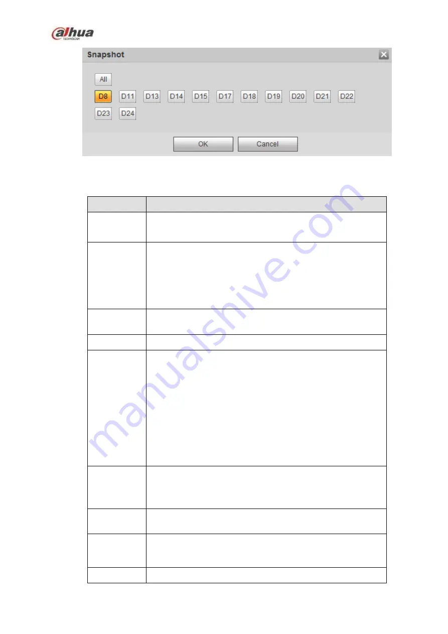
Figure 5-64
Please refer to the following sheet for detailed information.
Parameter
Function
Enable
You need to check the box to enable motion detection function.
Please select a channel from the dropdown list.
Period
Motion detection function becomes activated in the specified
periods. See Figure 5-60.
There are six periods in one day. Please draw a circle to enable
corresponding period.
Click OK button, system goes back to motion detection interface,
please click save button to exit.
Anti-dither
System only memorizes one event during the anti-dither period.
The value ranges from 5s to 600s.
Sensitivity
There are six levels. The sixth level has the highest sensitivity.
Region
If you select motion detection type, you can click this button to set
motion detection zone. The interface is shown as in Figure 5-61.
Here you can set motion detection zone. There are four zones for
you to set. Please select a zone first and then left drag the mouse
to select a zone. The corresponding color zone displays different
detection zone. You can click Fn button to switch between the arm
mode and disarm mode. In arm mode, you can click the direction
buttons to move the green rectangle to set the motion detection
zone. After you completed the setup, please click ENTER button to
exit current setup. Do remember click save button to save current
setup. If you click ESC button to exit the region setup interface
system will not save your zone setup.
Record
channel
System auto activates motion detection channel(s) to record once
an alarm occurs. Please note you need to set motion detect record
period and go to Storage-> Schedule to set current channel as
schedule record.
Record Delay System can delay the record for specified time after alarm ended.
The value ranges from 10s to 300s.
Alarm out
Enable alarm activation function. You need to select alarm output
port so that system can activate corresponding alarm device when
an alarm occurs.
Latch
System can delay the alarm output for specified time after an
Содержание NVR1A-4P Series
Страница 1: ...Dahua Network Video Recorder User s Manual V 4 3 0 ...
Страница 138: ...124 Figure 3 5 3 6 6 NVR42N Series Please refer to Figure 3 6 for connection sample Figure 3 6 ...
Страница 142: ...128 Figure 3 11 3 6 12 NVR42V 8P Series Please refer to Figure 3 12 for connection sample ...
Страница 143: ...129 Figure 3 12 ...
Страница 157: ...143 Figure 4 15 Step 2 Click device display edit interface See Figure 4 16 ...
Страница 220: ...206 Figure 4 93 Figure 4 94 ...
Страница 240: ...226 Figure 4 110 Figure 4 111 Figure 4 112 ...
Страница 251: ...237 Figure 4 123 Figure 4 124 ...
Страница 253: ...239 Figure 4 126 Click draw button to draw the zone See Figure 4 127 ...
Страница 257: ...243 Figure 4 130 Click Draw button to draw a zone See Figure 4 131 Figure 4 131 ...
Страница 262: ...248 Figure 4 136 Click draw button to draw the zone See Figure 4 137 ...
Страница 275: ...261 Figure 4 148 Figure 4 149 ...
Страница 276: ...262 Figure 4 150 Figure 4 151 ...
Страница 387: ...373 Figure 5 60 Figure 5 61 ...
Страница 388: ...374 Figure 5 62 Figure 5 63 ...
Страница 412: ...398 Figure 5 96 Figure 5 97 ...
Страница 418: ...404 Figure 5 106 5 10 4 4 Record Control The interface is shown as in Figure 5 107 Figure 5 107 ...


