background image

Local  Configurations


52


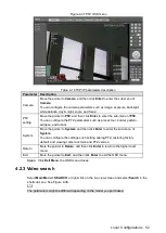
 PTZ OSD menu 

Figure 4-37


Table 4-16 TCP/IP parameters description 

Parameter  Description 

Camera 

Move the pointer to 

Camera

, and then click 

Enter

 to enter the sub-menu of 

Camera

You can configure the camera parameters such as image, exposure, backlight, 

white balance, day & night, zoom, and focus. 

PTZ 

setting 

Move the pointer to 

PTZ

, and then click 

Enter

 to enter the sub-menu of 

PTZ

You can configure the PTZ parameters such as preset, tour, border, pattern, 

autopan, and reboot. 

System 

Move the pointer to 

System

, and then click 

Enter

 to enter the sub-menu of 

System

You can configure the settings such setting analog PTZ, restoring factory 

default, and viewing camera version and PTZ version. 

Return 

More the pointer to 

Return

, and then click 

Enter

 to return to the higher level 

menu. 

Exit 

More the pointer to 

Exit

, and then click 

Enter

 to exit the OSD menu. 

  Click

 Exit Menu

, the OSD menu closes. 

Step 3

4.2.3 Video search 

Select 

Main Menu > SEARCH

, or right-click on the live view screen and select 

Search

 in the 

shortcut menu. See Figure 4-38. 


The parameters might be different depending on the model you purchased. 

Содержание MCVR6204

Страница 1: ...Mobile Digital Video Recorder User s Manual V1 0 0 ...

Страница 2: ...s remotely These ports can be changed to any set of numbers between 1025 65535 Avoiding the default ports reduces the risk of outsiders being able to guess which ports you are using 3 Enable HTTPS SSL Set up an SSL Certificate to enable HTTPS This will encrypt all communication between your devices and recorder 4 Enable IP Filter Enabling your IP filter will prevent everyone except those with spec...

Страница 3: ...ot using it If you are using SNMP you should do so only temporarily for tracing and testing purposes only 12 Multicast Multicast is used to share video streams between two recorders Currently there are no known issues involving Multicast but if you are not using this feature deactivation can enhance your network security 13 Check the Log If you suspect that someone has gained unauthorized access t...

Страница 4: ... the guide may cause harmful interference to radio communication For class A device these limits are designed to provide reasonable protection against harmful interference in a commercial environment Operation of this equipment in a residential area is likely to cause harmful interference in which case the user will be required to correct the interference at his own expense For class B device thes...

Страница 5: ...avoided could result in property damage data loss lower performance or unpredictable result TIPS Provides methods to help you solve a problem or save you time NOTE Provides additional information as the emphasis and supplement to the text Revision History No Version Revision Content Release Time 1 V1 0 0 First release July 27 2018 Privacy Protection Notice As the device user or data controller you...

Страница 6: ... written notice The product updates might cause some differences between the actual product and the Manual Please contact the customer service for the latest program and supplementary documentation There still might be deviation in technical data functions and operations description or errors in print If there is any doubt or dispute please refer to our final explanation Upgrade the reader softwar...

Страница 7: ...allowed humidity and temperature conditions Do not expose the Device to water or excessive moisture when washing the car A failure to follow this instruction might result in short circuit fire or other malfunctions The dust on the circuit board will cause short circuit which affect the normal operation of the Device and even damage the Device To make the Device work stably for a long time please r...

Страница 8: ...ce to video and audio signals and avoid electrostatic or induced voltage to damage the Device Please unplug the power cable before you remove the audio video signal cable RS 232 or RS 485 cable otherwise these ports might be damaged Make sure the positive pole and negative pole of the power supply are connected correctly The ACC signal line must connect to the vehicle key The output voltage from v...

Страница 9: ...6 2 6 1 Alarm Port Introduction 15 2 6 2 Alarm Input Port 15 2 6 3 Alarm Output Port 16 3 Turning On Off the Device 18 Turning On the Device 18 3 1 Turning Off the Device 18 3 2 4 Local Configurations 19 Initial Settings 19 4 1 4 1 1 Initializing Device 19 4 1 2 Logging the Device 21 4 1 3 Configure IP Address and Port 22 4 1 4 Configuring General Settings 25 4 1 5 Configuring Remote Devices 27 4 ...

Страница 10: ...ing Detect Type 138 5 1 7 Configuring Record Settings 139 5 1 8 Configuring Recording Schedule 140 5 1 9 Configuring Snapshot Schedule 143 Function Modules Operations 144 5 2 5 2 1 Preview 144 5 2 2 Playback interface 153 5 2 3 Searching for Face Picture 159 5 2 4 Configuring Alarm Events Settings 161 Configuring System Settings 162 5 3 5 3 1 Remote Devices Configurations 163 5 3 2 Network Paramet...

Страница 11: ...Table of Contents X HDD Capacity Calculation 228 Appendix 2 ...

Страница 12: ...le hard disks extend the record storage time Built in power module makes installation easier PoE function provides power supply to the cameras Multiple alarm modes and record modes are supported Various information and vehicles status are collected and recorded Supports built in 3G 4G Wi Fi transmission and positioning modules Supports simultaneous output from AV port and VGA port Supports face re...

Страница 13: ...d PTZ control Alarm linkage Supports alarm output from multi channel relay switch on off which is convenient for alarm linkage and on site lighting control Supports protective circuit for alarm input port and alarm output port which protect the Device from damage Communication interface RS 485 port Controls the external devices RS 232 port Extend the connection of keyboard for matrix control Conne...

Страница 14: ...e video and encode video in network transmission to optimize the coding of network transmission which improves the control capability of wireless network transmission Vehicle status record Provides seven external alarm ports and two pulse ports that can connect to signals such as door signal cornering lamp signal reversing signal and braking signal to give an indication and take a record ...

Страница 15: ...g transportation Secondly open the accessory box to check if the accessories are complete against the packing list Instructions about front panel rear panel and labels The functions of indicator lights and ports are described in the later chapter of the Manual The labels on the Device are very important for our after sales service To ensure the after sales service please keep the labels well and d...

Страница 16: ...tatus indicator Glows blue when there is HDD installed and the indicator is off when there is no HDD 6 ALM Alarm status indicator Glows blue when there an alarm event and the indicator is off when there is no alarm 7 IR Receives infrared signal from remote control 8 GPS GPS status indicator Glows blue when GPS positioning is working properly and the indicator is off when GPS function is not enable...

Страница 17: ...signals This function is supported on the Device with positioning module 5 Wi Fi1 antenna port Connects to Wi Fi antenna for receiving Wi Fi signals Wi Fi2 antenna port Reserved port 6 3G 4G antenna port Connects to 3G 4G antenna for receiving 3G 4G signals This function is supported on the Device with 3G 4G modules 7 Voice talk port Connects to voice talk device For details see Voice Talk Port in...

Страница 18: ...ire VGA port VGA port Figure 2 3 No Function No Function No Function 1 12V 1A output 5 Audio output 9 VGA line sync 2 Ground line 6 VGA_B 10 VGA line sync 3 VGA_G 7 VGA_R 4 RXD_232 8 TXD_232 Video and audio output port Video and audio output port Figure 2 4 No Function No Function 1 12V 1A output 3 Audio output 2 Ground line 4 Video output EXTEND port EXTEND port Figure 2 5 Name Function 5 USB 5V ...

Страница 19: ... connects to RS 232 port TX Voice talk port Voice talk port Figure 2 6 Name Function 12 12V output Ground Mic In that can connect to microphone Mic Out that can connect to earphone SPK Speak positive pole SPK Speak negative pole External pickup port External pickup port Figure 2 7 Name Function 12 12V output Ground Mic In that can connect to pickup Connects to earphone ...

Страница 20: ...slot Step 3 SIM card and SD card installation Figure 2 8 After installation make sure the cover is put back and fixed firmly to avoid damage from installing and taking out the HDD Insert the HDD box Step 4 Installing HDD 2 4 The HDD is not our standard accessory Please purchase separately if needed Before the installation is completed make sure the Device is disconnected from power and do not plug...

Страница 21: ...g HDD Information Figure 2 9 Remove the HDD box cover Remove the screws the rear panel and then the Step 2 enclosure HDD box rear panel removing Figure 2 10 HDD box rear panel enclosure Figure 2 11 Remove HDD brackets Step 3 ...

Страница 22: ...ackets with eight screws and then fix the brackets to holding bracket Step 4 with two screws See Figure 2 13 HDD box installation 1 Figure 2 13 Install HDD box enclosure in place along the rails and then fix the HDD box rear panel Step 5 with two screws See Figure 2 14 ...

Страница 23: ...eo data Install the water proof connector when connecting cables Take the waterproof connector from the accessory bag and then install the rubber Step 1 sleeve into the waterproof connector along the arrow See Figure 2 15 Gasket installation Figure 2 15 Pull the network cable through the waterproof connector rubber sleeve and waterproof Step 2 endcap in sequence and make the Ethernet plug See Figu...

Страница 24: ...erproof connector fastening Figure 2 18 See Figure 2 19 for the connected waterproof connenctor Connection completed Figure 2 19 2 5 2 Audio and Video Output Port The four cored aviation port Figure 2 20 can output the video and audio data Four cored aviation port Figure 2 20 No Function 1 12V external power source and no more than 1 5A 2 Ground line 3 Audio port 4 Video port ...

Страница 25: ...nput The alarm input port supports alarm signal from ground and device of 12V 24V voltage If the alarm device is connected to the Device and other devices use relay for isolation Alarm Output The alarm output port cannot be connected to high power load less than 1A When constructing the output circuit the excessive current should be prevented from causing damage to the relay Use the contactor for ...

Страница 26: ... line CTRL 12V 12V 0 75A output with switch control A B RS 485 port that connects to speed dome with PTZ function 2 6 2 Alarm Input Port Both NO and NC are supported The GND of alarm detector is in parallel connection with COM the power supply of alarm detector should be from external power source See Figure 2 22 The GND of alarm detector is in parallel connection with GND of Device Connect the NC...

Страница 27: ... type 1Z Contact resistance 100mΩ 0 1A 6VDC Contact material AgNi Gold plated Contact load resistive 0 5A 125V AC 1A 30V DC Maximum switching voltage 125V AC 60V DC Maximum switching current 2A Maximum switching power 62 5VA 30W Minimum allowable load 1mA 5V Mechanical durability 1 107 times 300 times min Electrical durability 1 105 times 30 times min Performance parameter Insulation resistance 10...

Страница 28: ...7 Vibrate 10Hz 55 Hz 3 3mm double amplitude Humidity 98 RH 40 Temperature range 30 70 Weight About 2 2g Leading out end mode DIP Packaging method Plastic Coil parameter Rated coil power Standard 200mW Sensitive 150mW ...

Страница 29: ...ff according to the settings of auto turning on off and auto turning off delay For details see 4 4 3 Automatic Maintenance If you have set the time for both auto turning on and turning off there are two situations when the ACC is disconnected If the system time is between the auto turning on and turning off the Device is turned off by the configured time If the system time is before the auto turni...

Страница 30: ...e Device and the external devices connected to the Device and to prolong the service life we recommend that you should refer to the national related standard to use the power source that provides stable voltage with less interference from ripples Plug in the power cable to the Device Step 1 After the Device is turned on the initialization interface is displayed See Figure 4 1 Initializing the Devi...

Страница 31: ...meters for password Step 4 If you do not want to configure the settings clear both the Email Address check box and the Security Question check box Email Address In the Email Address box enter an email address for password reset In case you forgot password enter the security code that you will get from this reserved email address to reset the password of admin Select the Security Question check box...

Страница 32: ...ing initializing the unlock pattern login interface is displayed Then draw an unlock pattern to login Click to view the password hint to help you remember the password If you forgot the password click to reset the password though security questions or the reserved email address For details see 4 3 6 7 Resetting password In the User Name list select a user account and enter the corresponding passwo...

Страница 33: ...nnect the Device to the network and make sure the Device can communicate with other devices in the network diagram Preparation Make sure the Device is connected to the network properly Procedure Select Main Menu SETTING NETWORK Step 1 The NETWORK interface is displayed See Figure 4 6 ...

Страница 34: ... to set the IP address gateway and subnet mask If DHCP is effective the obtained value will display in the IP Address box Subnet Mask box and Gateway box If DHCP is not effective 0 will be displayed To view the current IP address if DHCP is not effective you can disable DHCP to display the IP address information that is not obtained by DHCP if DHCP is effective disabling DHCH will not display the ...

Страница 35: ...t instruction Rtsp user name password IP address port cam realmonitor channel 1 subtype 0 Username For example admin Password For example admin_123 IP address For example 192 168 1 16 Port The default setting is 554 If the default setting is displayed you do not need to configure this parameter Channel Numbers from 1 For example if it is channel 2 then enter channel 2 Subtype stream type The main ...

Страница 36: ...ed double click on the service option the corresponding setting interface is displayed For details see 4 3 2 Configuring Network Service Settings 3 Click Save Click Save Step 4 4 1 4 Configuring General Settings You can configure the system general settings such as system time date format and language Select Main Menu SETTING GENERAL Step 1 The GENERAL interface is displayed See Figure 4 8 ...

Страница 37: ...e the Device is located 1 Select the DST check box 2 Click Setup The DST interface is displayed 3 According to the local regulations configure the type begin time and end time for the DST 4 Click Save Timing Mode You can configure how to calibrate the system time 1 Click Timing Mode The Timing Mode interface is displayed 2 Select a timing mode DSS The system time syncs with DSS platform GPS Config...

Страница 38: ...es there is not standby time for the Device Preview Bar Select the position of preview bar in the live view screen Top or Bottom Startup Wizard Select the Startup Wizard check box the system enters the startup wizard interface in next booting up otherwise the system enters login interface directly IPC Time Sync You can select the IPC Time Sync check box and enter the interval for IPC sync with the...

Страница 39: ...hen click Initialize Step 4 The password setting interface is displayed See Figure 4 10 Password setting Figure 4 10 Configure the password by either of the following two ways Step 5 Select the Using current device password and email info check box the remote device will use the password and email info of the Device You can also manually set the password for remote device 1 Clear the Using current...

Страница 40: ...rd and enter it again in the Confirm Password box Click Next The security setting interface is displayed See Figure 4 12 Security setting Figure 4 12 3 In the Email Address box enter the email address If you do not want to configure this setting clear the check box Click Next Step 6 The Device starts initializing After initialization is completed see Figure 4 13 ...

Страница 41: ...hen click Right click on the live view screen the shortcut menu is displayed Select Remote Device Add a remote device Step 2 Select the check box of an added remote device and then click Delete By search 1 Click IP Search the searched devices are displayed 2 Double click on an IP address or select the check box and then click Add The remote device is displayed in the Added Device area After the co...

Страница 42: ... is 80 TCP Port TCP service port The default setting is 37777 You can configure this parameter according to your actual situation Username Enter the user name and password for login the remote device If the remote device was not added before the password of remote device is the one that was set during initializing Please modify the password if needed Password Remote Channel Select the channel numb...

Страница 43: ...ains the user name which is admin by default Enter the IP address of remote device according to your network plan Step 4 Click Save Step 5 After modification the new IP address is displayed in the Added Device area 4 1 6 Configuring Channel Type After the camera is connected to the Channel 1 to Channel 8 the system recognizes the corresponding channel type You can modify the channel type if needed...

Страница 44: ...ode You can also enable or disable snapshot function Auto The recording starts automatically according to the record type and recording time as configured in the recording schedule Manual recording Keep general recording for 24 hours for the selected channel Manual recording operation requires the user have the permission to access STORAGE settings Different camera corresponds to different channel...

Страница 45: ...nual Schedule Stop Select the record mode Manual Top priority When the Manual check box is selected the system keeps general recording for 24 hours for the corresponding channel Schedule The system starts recording according to the record type and recording time as configured in the SETTING SCHEDULE Stop Do not record Enable Disable Enable or disable the scheduled snapshot for the corresponding ch...

Страница 46: ...edule Figure 4 18 Configure the parameters For details see Table 4 5 Step 2 Table 4 5 Record schedule parameters description Parameter Description Channel Select a channel to configure the corresponding recording schedule If you configure the same setting for all channels select All Pre record Start recording for 0 seconds to 30 seconds before the alarm event occurs If you enter 0 seconds there wi...

Страница 47: ...he Manual check box for corresponding channel The redundancy HDD works like a backup HDD for recorded videos but it will not back up snapshots Copy Click Copy to copy the settings to other channels Configure the period and alarm type The alarm type includes Regular MD and Step 3 Alarm If the MD check box and the Alarm check box are selected the corresponding alarm linkage should be enabled For det...

Страница 48: ...perature of vehicle Displays the speed of vehicle where the Device is located Displays the connection status of 3G 4G network For details about setting the 3G 4G network see 4 3 3 2 1 Configuring 3G 4G Settings Indicates 3G 4G connection failed Indicates 3G 4G connection succeeded Indicates the Wi Fi connection status For details about setting the Wi Fi network see 4 3 3 2 2 Configuring Wi Fi Netw...

Страница 49: ...rs 3 This icon displays when the video loss is detected 4 2 1 2 Live View Control bar When you move the pointer to a channel window the live view control bar is displayed See Figure 4 20 If there is not operation for six seconds after the control bar is displayed the control bar hides automatically Live View Control bar Figure 4 20 Click the icon switches to Hold down the left mouse button to sele...

Страница 50: ...rd files or pictures Record Open the record interface For details see 4 1 7 Configuring Record Settings Remote Device Search and add a remote device Alarm Out Open the alarm out interface where you can configure the alarm output type For details see 4 3 4 4 Configuring Alarm Output Settings Alarm View the alarm status of each channel Device Open the device information display interface For details...

Страница 51: ...higher the percentage the more transparent the local menus will become Channel Name Configures the channel name 1 Click Modify The Channel Name interface is displayed 2 In the Channel Name list select Local Local The channel name that is displayed on the Device local interface Remote The channel name that is displayed on the web interface of camera 3 Modify the channel name if needed 4 Click Save ...

Страница 52: ...annel 12 You can modify if needed 3 Click Save Split Mode Configure the split mode of live view screen and set the interval from other split mode to the configured split mode If you select View 1 you need to select the corresponding channel If you select multi channel view you need to select all the channels When the other split mode stays up to the end of interval the configured split mode is dis...

Страница 53: ...lete the channel group Select the check box of any channel group and then click Up or Down to adjust the position of channel group Click Save Step 5 The DISPLAY interface is displayed Click OK Step 6 4 2 1 4 3 Configuring Zero Channel Settings You can configure the encode mode resolution frame rate bite rate and overlay information for zero channel view You can view several video sources on one ch...

Страница 54: ...ard The Device only supports H 264 Resolution In the Resolution list select the video resolution The higher the value is the better the image quality will become Frame Rate Configure the frames per seconds for video The larger the value is the smoother and more vivid the image will be Bit Rate Select a value for bit rate of video Window Split Select the window split mode and channel for recoding u...

Страница 55: ... PTZ functions This function is supported only on the camera with PTZ function Before operating PTZ please make sure the Device is connected to PTZ 4 2 2 1 Configuring PTZ Connection Settings You need to configure the PTZ connection settings before use Select Main Menu SETTING PTZ Step 1 The PTZ interface is displayed In the Channel list select a channel Step 2 In the PTZ Type list select PTZ type...

Страница 56: ...ot be controlled from the Device Baud Rate Select the baud rate for the PTZ camera Data Bit The default value is 8 Stop Bit The default value is 1 Parity The default value is None If Channel 9 to Channel 12 is selected in the PTZ Type list select Remote See Figure 4 27 PTZ settings Remote Figure 4 27 Click Save Step 4 Click Copy to copy the settings to other channels 4 2 2 2 Working with PTZ Contr...

Страница 57: ... to open the PTZ functions settings interface You can configure preset tour pattern and border For details see 4 2 2 3 Configuring PTZ Functions PTZ Trace Click PTZ Trace the live view screen is displayed Drag to view the image in the channel window connected with PTZ camera the PTZ camera turns to the direction you drag to Pg Switch Click Pg Switch to switch the PTZ setting interface For details ...

Страница 58: ... Del Preset to delete the preset To modify the preset select the preset and move the camera to the direction that you need 4 2 2 3 2 Configuring Tours The PTZ camera repeats performing tours among the configured presets after configuration On the PTZ control panel click Set Step 1 The PTZ function settings interface is displayed Click the Tour tab Step 2 The Tour interface is displayed See Figure ...

Страница 59: ...Pattern tab Step 2 The Pattern interface is displayed see Figure 4 32 Pattern Figure 4 32 In the Pattern box enter the value for pattern Step 3 Click Start Step 4 The PTZ control panel is displayed You can perform the operations such as directions movement zoom and focus Step 5 adjustment On the PTZ control panel click Set Pattern End Step 6 4 2 2 3 4 Configuring Borders The PTZ camera automatical...

Страница 60: ...d then click Preset Then you can quickly move the PTZ camera to the corresponding position The preset includes the information such as horizontal angle lateral angle and focus of PTZ camera Pattern In the No box enter a pattern number and then click Pattern The PTZ camera repeats movement according to the configured operations The operation records include the information such as the manual operat...

Страница 61: ... and click Off to turn off the light Controls the screen wiper of external device through RS 485 command To use this function make sure it is supported on the external device In the function list select Screen Wiper Click On to turn on the screen wiper and click Off to turn off the screen wiper Controls the warming up module of external device through RS 485 command To use this function make sure ...

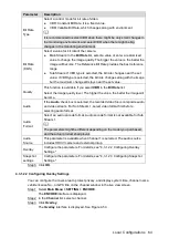
Страница 62: ...ameter Description Enter Menu Click Enter Menu the OSD menu is displayed on the channel window Click Exit Menu the OSD menu closes Click Exit Menu the OSD menu closes Click or to move the pointer to the item you want to configure on the OSD menu When the pointer has selected an item click or to configure this item Enter If there is sub menu for an item click Enter to enter the sub menu More the po...

Страница 63: ...order pattern autopan and reboot System Move the pointer to System and then click Enter to enter the sub menu of System You can configure the settings such setting analog PTZ restoring factory default and viewing camera version and PTZ version Return More the pointer to Return and then click Enter to return to the higher level menu Exit More the pointer to Exit and then click Enter to exit the OSD...

Страница 64: ...er playing the time bar adjusts based on the current playing time point Time bar colors Green indicates general record Red indicates external alarm Yellow indicates motion detection 4 Playing status Includes two playback status Play and Stop 5 Sync Select the Sync check box to simultaneously play recorded videos of different channels in the same period in multi channel view If the playback time of...

Страница 65: ...details see 4 2 3 4 Clipping Recorded Video 12 Time bar unit You can select 24hr 2hr 1hr or 30min as the unit of time bar The time bar display changes with the setting 4 2 3 1 Introducing Playback Controls Bar You can perform the operations such as control the speed of playback and take snapshots through the playback controls bar See Figure 4 39 and Table 4 18 Playback controls bar Figure 4 39 The...

Страница 66: ... the area that you want to enlarge The area is enlarged after the left mouse button is released Right click on the screen to exit zoomed in status Point to the center of the area that you want to enlarge move the wheel button to zoom in the area After entering the zoomed in status you can drag the enlarged area to move to any directions to view details of other parts of image Right click on the en...

Страница 67: ...re is a redundancy HDD on the Device The redundancy HDD is supported only when there is a redundancy HDD on the Device For details about redundancy HDD operations see 4 3 7 1 Configuring HDD Information From R W HDD Play back recorded videos from local HDD of the Device From redundancy HDD Play back recorded videos from redundancy HDD of the Device if it is supported For details about configuring ...

Страница 68: ... Play back snapshots from local HDD of the Device From redundancy HDD Play back snapshots from redundancy HDD of the Device if it is supported Select the month year and channel number that you want to search Step 2 Select a date Step 3 Click Step 4 The system is playing back snapshots according to the configured interval 4 2 3 3 2 Playing Back Snapshots by File List In the search type list select ...

Страница 69: ...erval 4 2 3 4 Clipping Recorded Video During playback clip sections of recorded video and save to the external storage such as USB flash disk For the video clip interface see Figure 4 43 Video clip Figure 4 43 Select a recorded video and click to start playing back Step 1 Click on the time bar to select the start time and then click to start clipping Step 2 Click on the time bar to select the end ...

Страница 70: ...e 4 44 Select the recorded video files that you want to back up Step 5 Click Backup to back up the files Step 6 4 2 3 5 Configuring Backup Settings You can back up the recorded video file into the external storage device Preparation Make sure the external storage device such as USB flash disk is connected to the Device Procedure Select Main Menu BACKUP Step 1 The BACKUP interface is displayed See ...

Страница 71: ... then click Format to clear the data in the external storage device Select the external storage device and then click Switch To R W to transfer the external storage device to the record storage HDD The system automatically saves the recorded videos to the external storage device During backup click Stop to stop backing up Click Backup Step 3 The BACKUP interface is displayed See Figure 4 46 Backup...

Страница 72: ...thin the configured time period Make sure the sufficient space in the external storage device Recorded files backup Figure 4 47 Click Start to start backing up recorded files Step 6 There is a progress bar to indicate the process After backup is completed the system prompt success message Click OK to complete backup You can view the backup files on PC The file format is Channel number_Record Type_...

Страница 73: ...usts the image contrast The bigger the value is the more obvious the contrast between the light area and dark area will become Saturation Adjusts the color darkness Adjust the saturation according to the actual situation The bigger the value the lighter the color will become Sharpness Adjusts the sharpness of image edge The bigger the value is the more obvious the image edge will become Gain Adjus...

Страница 74: ...tion Parameter Description Channel In the Channel list select a channel Record type In the Type list select General MD Motion Detect or Alarm The three types correspond to different parameters Compression Displays the video encode standard Smart Code Enable the smart code function This function can reduce the video bit stream to maximize the storage space Resolution In the Resolution list select t...

Страница 75: ... The higher the value the better the image will become Audio If the Audio check box is selected the recorded video file is composite audio and video stream For Sub Stream 1 select video format first before selecting audio format Audio Format Select an audio encode format Audio encode format is not available for Sub Stream 1 The parameters might be different depending on the model you purchased and...

Страница 76: ...eb or during recording Monitor The covered area is invisible when output to VGA monitor or small screen but visible when output to web or during recording 2 Click the buttons to select blocks and then click Setup 3 Drag the block to the area that you want to cover and adjust the size of the block Right click on the screen to return to Overlay interface You can also change the size and position of ...

Страница 77: ...Mode list select Regular or Trigger Regular Take a snapshot within the configured time period Trigger Take a snapshot when there is a video detection event occurs Image Size Select a resolution for the captured image Image Quality Configures the image quality by six levels The higher the level the better the image will become Interval Configure the snapshot frequency The maximum value you can set ...

Страница 78: ...ep 5 The ENCODE interface is displayed Click OK Step 6 4 3 1 3 Viewing Status of Remote Device You can view the remote device information such as connection status IP address and alarm events This function is supported only on Channel 9 to Channel 12 Select Main Menu INFO REMOTE DEVICE INFO The Channel Status interface is displayed See Figure 4 53 For the status icons description see Table 4 23 ...

Страница 79: ...e alarm status for motion detect video loss tampering and external alarms No alarm from remote device Alarm Video loss alarm Motion detection alarm Video tampering alarm Video Loss Tampering Alarm In Channel Name Displays the channel name of remote device Manufacturer Displays the manufacturer of remote device Type Displays the type of remote device 4 3 1 4 Viewing Connection Log of Remote Device ...

Страница 80: ... 1 Configuring DDNS Settings When the IP address of the Device changes frequently the DDNS function can dynamically refresh the correspondence between the domain on DNS and the IP address ensuring you access the Device by using the domain Preparation Make sure the type of DNS supported by the Device has been obtained Login the website provided by the DDNS service provider to register the informati...

Страница 81: ... Domain Name The domain name for registering on the website of DDNS service provider Username Enter the user name and password obtained from DDNS service provider You need to register including user name and password on the website of DDNS service provider Password Interval The connection interval between the Device and DDNS server Test Click Test to check whether the registration is succeeded 4 C...

Страница 82: ...ls see Table 4 26 Password Sender Enter the sender s email address Receiver Enter the email address of mail receiver You can enter maximum three email addresses separated by colon Subject Supports Chinese English and Arabic numerals You can enter maximum 63 characters Encrypt In the Encrypt list select an encryption type from NONE SSL and TLS For details see Table 4 26 Event Interval This is the i...

Страница 83: ...type Port Description QQ smtp qq com SSL 465 Do not select NONE for encrypt type The mailbox must have applied SMTP service The password must be an authorized password Both the QQ login password and email login password are invalid Obtain the authorized password when your mailbox is applying for SMTP service TLS 587 163 smtp 163 com SSL 465 994 The mailbox must have applied SMTP service The passwo...

Страница 84: ...NETWORK interface is displayed Click NETWORK SETTING Step 2 The NETWORK SETTING interface is displayed Configure FTP settings Step 3 1 Double click FTP The FTP interface is displayed See Figure 4 57 FTP Figure 4 57 2 Configure the parameters For details see Table 4 27 Table 4 27 FTP parameter description Parameter Description Server IP IP address of the PC that is installed with FTP server Port Th...

Страница 85: ...mple the interval is 5 seconds and snapshot interval is 10 seconds per snapshot the system uploads the snapshot every 10 seconds You can configure the snapshot interval For details see 4 3 1 2 3 Configuring Snapshot Settings Channel Select the channel that you want to apply the FTP settings Weekday Select the week day and set the time period that you want to upload the recorded files You can set t...

Страница 86: ...ure 4 58 2 On your mobile phone open the DMSS app 3 Scan the device serial number to add the device to DMSS Please scan the QR code on the actual interface of Device 4 Select the Enable check box 5 Click Save After connection succeeded you can view the connection status of device Select the P2P check box and then click Save Step 4 The NETWORK interface is displayed Click OK Step 5 Adding Device in...

Страница 87: ...to PoE port of Device the Switch will automatically allocate IP address to the IP camera and then the Device can get connected to this IP camera This function is supported only by the Device with PoE port The Switch cannot be connected to PoE port otherwise the connection will fail By default the Switch Settings check box is enabled The network segment is 10 1 1 1 It is recommended to keep the def...

Страница 88: ...ons Operation Description Use network Cable to connect IP camera to PoE port After connecting the Device configures an IP address to the IP camera This IP address is from the network segment where the Switch is located Try to configure the IP address by arp ping If the DHCP function is enabled use DHCP to configure the IP address After the IP address is configured a broadcast will be sent from Swi...

Страница 89: ...al channel that corresponds to PoE port should not be occupied 4 3 2 6 Configuring Network Testing Settings You can test the network status and load 4 3 2 6 1 Testing Network Status You can test the network status and view the average delay and packet loss rate Select Main Menu INFO NETWORK NET TEST Step 1 The NET TEST interface is displayed See Figure 4 61 Net test Figure 4 61 In the Destination ...

Страница 90: ...ing speed and sending speed Select Main Menu INFO NETWORK NET LOAD Step 1 The NET LOAD interface is displayed See Figure 4 63 Network load Figure 4 63 Click the network port that you want to view The data receiving speed and sending Step 2 speed information are displayed By default the system displays the network load of eht0 You can view the load of only one network port at one time ...

Страница 91: ...vice is accessed to the Platform the system reports the MAC information to the Platform by the configured interval Select Main Menu VEHICLE WIFI Step 1 The WIFI interface is displayed In the Function Type list select Mac Step 2 The Mac setting interface is displayed See Figure 4 64 Mac setting Figure 4 64 In the Upload Interval box enter the interval Step 3 Configure this parameter when the Device...

Страница 92: ...played See Figure 4 65 Mac information Figure 4 65 4 3 3 1 3 Backing Up MAC Information Select Main Menu ADVANCED Mac Info Step 1 The Mac Info interface is displayed After the MAC information satisfying the searching conditions is displayed click Step 2 Backup The Backup interface is displayed See Figure 4 66 Backup Figure 4 66 Click Start Step 3 ...

Страница 93: ...can receive the information such as alarm information audio and video image and device status Preparation Make sure the Device is equipped with 3G 4G module and inserted with SIM card from the Communication Operator The dial number user name and password have been obtained from the Communication Operator Procedure Select Main Menu VEHICLE 3G 4G Step 1 The 3G 4G interface is displayed See Figure 4 ...

Страница 94: ...ch is used to distinguish the 3G 4G modules among Communication Operators such as WCDMA and CDMA1x APN Access Point Name After enabled the access point of Communication Operator is displayed If you select Customized manually enter the APN information in the box AUTH Authentication mode includes three protocols PAP CHAP and NO_AUTH The system automatically recognizes and displays the protocol Dial ...

Страница 95: ...ected to Wi Fi Procedure Select Main Menu VEHICLE WIFI Step 1 The WIFI interface is displayed In the Function Type list select Wifi Step 2 The Wi Fi setting interface is displayed See Figure 4 68 After rebooted the Device will automatically connect to the hotspot that was connected recently successfully Wi Fi setting Figure 4 68 Connect to Wi Fi Step 3 After the Device is connected to Wi Fi the mo...

Страница 96: ...sk and gateway 3 Click Save After the connection succeeded the Wi Fi icon in the bottom right of the live view screen shows connected status When WPA or WPA2 is selected in the Verification list Auto is displayed The verification type WEP and TKIP are not supported because they are not safe It is recommended to use WPA or WPA2 4 3 3 2 3 Configuring Wi Fi Hotspot The Device can work as a hotspot to...

Страница 97: ...Figure 4 71 WIFI AP Figure 4 71 Enter SSID information select work band and verification type and then enter the Step 4 connection password In the Work Band list you can select 2 4G or 5G Select the Connection Password check box the clear text password is displayed The default password is 12345678 Click Save Step 5 ...

Страница 98: ...rver number If there is more than one DSS connected you can configure the parameters for different DSS by selecting the corresponding number Server IP In the Server IP box enter the IP address or domain name of server to register Port Enter the port of the server for register ID Unique ID for identifying Device When different Devices register to the same server the IDs should be different Username...

Страница 99: ...peed Displays the current vehicle speed Mileage The parameter for modifying mileage error Mileage Cumulation Select the vehicle mileage cumulation mode Mileage Displays the total mileage Start Mileage In the Start Mileage box enter the initial mileage of vehicle Speed source In the Speed source list select where the speed is obtained including No source Pulse 1 Position Info and Pulse 1 Position I...

Страница 100: ...ad and tilt angle of slope Step 2 Click Reset to rectify the position of vehicle You can judge if there is any collision or rollover through acceleration and gyro indications You can view the Device internal temperature Click OK Step 3 4 3 3 6 Configuring Position Report You can configure the position report strategy to be device auto report or report per platform schedule Select Main Menu VEHICLE...

Страница 101: ...The system reports vehicle position to platform only if one of conditions is satisfied Report by Distance Inflexion Angle Report Interval When ACC off When the vehicle ACC status is off the system report the position to platform according to the configured report interval Platform schedule In the Report Strategy list select Platform Schedule The Platform Schedule setting interface is displayed See...

Страница 102: ... of information in the Details area After the connection resumes the Device will upload the position information that occurred when the connection was broken to the platform Click OK Step 3 4 3 4 Configuring Alarm Events Settings You can configure the alarm settings such as alarm input settings video detection system events and alarm output settings 4 3 4 1 Configuring Alarm Input Settings You can...

Страница 103: ...gure this parameter Normal Open The alarm signal is disconnected normally The alarm is activated when alarm signal is closed Normal Close The alarm signal is closed normally The alarm is canceled when alarm signal is disconnected Trigger If Local Alarm is selected configure this parameter High The alarm signal is 12V 24V voltage Low The alarm signal is signal ground Alarm Name If Local Alarm is se...

Страница 104: ...recording for alarm is enabled For details see 4 1 8 Configuring Recording Schedule The auto recording is enabled For details see 4 1 7 Configuring Record Settings Delay Set a length of time for the Device to delay turning off alarm after it is canceled The value ranges from 10 seconds through 300 seconds Tour Select the Tour check box and the channels When an alarm event occurs a tour of the sele...

Страница 105: ...s the system activates the alarms and links the configured actions Tampering When the camera lens is covered or the video is displayed in a single color because of the causes such as sunlight status the monitoring cannot be continued normally and in this case the system activates alarm Select the Enable check box Step 3 Configure the motion detection area Step 4 Perform this step if Motion Detect ...

Страница 106: ...fault setting Delay Motion If Motion Detect is selected configure this parameter Select the Delay Motion check box When the vehicle ACC status is off the motion detect function is enabled when the ACC status is on the motion detect function is disabled Anti dither If Motion Detect is selected configure this parameter Configure the event detection lasting time The system records only one event duri...

Страница 107: ...played on the Device local interface To use this function make sure the tour function is enabled and the corresponding settings are configured For details see 4 2 1 4 2 Configuring Tour Settings After tour is completed the live view screen stays on the current image of tour Snapshot Select the Snapshot check box and select a snapshot channel s When an alarm event occurs the corresponding channel s...

Страница 108: ...he vehicle ACC status is off the voltage supplied to the Device is lower than set minimum percentage the system generates alarm and links the configured actions Over Speed When the vehicle is driving faster than the set maximum speed the system generates alarm and links the configured actions Low Speed When the vehicle is driving slower than the set minimum speed the system generates alarm and lin...

Страница 109: ...s selected configure this parameter In the Threshold box enter the maximum acceleration value of vehicle Threshold If Rapid Slowdown is selected configure this parameter In the Threshold box enter the maximum deceleration value of vehicle Attempt s If Illegal Login is selected configure this parameter In the Attempt s box enter the maximum number of allowed password input errors If the number of p...

Страница 110: ...within three minutes Click Save Step 5 4 3 4 4 Configuring Alarm Output Settings Configuring Alarm Output Mode Select Main Menu ADVANCED ALARM OUT Step 1 The Alarm Out interface is displayed See Figure 4 81 Alarm Out Figure 4 81 When the Device activates alarms the connected alarm device generates alarms in the Step 2 way that you can configure in this section Manual After the alarm linkage is con...

Страница 111: ...responding channel Select Main Menu ADVANCED Face Detection Step 1 The Face Detection interface is displayed see Figure 4 82 Face detection Figure 4 82 In the Channel list select the channel that you want to enable the face detection Step 2 function Select the Enable check box Step 3 Click Save Step 4 4 3 5 Configuring RS 232 Port Parameters You can configure the RS 232 serial port parameters such...

Страница 112: ... Keyboard Use the dedicated keyboard to control the Device Adapter Connects directly to PC to transmit the data NetKeyboard Use the dedicated keyboard to control the Device or connect the Device to the network PTZ PTZMatrix Connects to the external matrix control ITS If MainCom is selected this port can connect to vehicle light and touch screen If Com1 is selected this port can connect to touch sc...

Страница 113: ... and the name cannot be repeated You can set maximum 64 users and 20 groups The default group name by User and Admin cannot be deleted You can set other groups and define the relevant permissions but the admin account cannot be set randomly Every user must belong to a group and one user only belongs to one group When selecting a group for a user the authority that the user can be given should be n...

Страница 114: ... Add user Figure 4 85 Configure the parameters For details see Table 4 37 Step 3 Table 4 37 Parameters description for adding user Parameter Description Reusable Select the check box user name can also be used to login the web Username Enter the user name and password and conform the password Password Confirm Password ...

Страница 115: ...unt Authority Click Save Step 4 The message pops up Click OK 4 3 6 2 Modifying a User You can modify the user account information such as memo MAC address group and authority For admin account you can configure the reserved email address and unlock pattern Select Main Menu ADVANCED ACCOUNT Step 1 The ACCOUNT interface is displayed Select a user and then click Modify User Step 2 The Modify User int...

Страница 116: ...4 87 Add group Figure 4 87 In the Name box enter a name for the group In the Memo box enter a description for Step 3 the group Then select authorities for the new group Click Save Step 4 The message pops up Click OK 4 3 6 4 Modifying a Group You can modify the group name memo and authority Select Main Menu ADVANCED ACCOUNT Step 1 The ACCOUNT interface is displayed Click Modify Group Step 2 The Mod...

Страница 117: ...message pops up Click OK 4 3 6 5 Modifying Password You can modify user password if needed Select Main Menu ADVANCED ACCOUNT Step 1 The ACCOUNT interface is displayed Click Modify Password Step 2 The Modify Password interface is displayed See Figure 4 89 Modify password Figure 4 89 In the User list select a user that you want to modify password In the Old Password Step 3 box the New Password box a...

Страница 118: ...configure the security questions and answers for resetting the password if needed Only Admin account supports this function Select Main Menu ADVANCED ACCOUNT Step 1 The ACCOUNT interface is displayed Click Security Question Step 2 The Security Question interface is displayed See Figure 4 90 Security question Figure 4 90 In the Question list select questions and then enter the answers in the Answer...

Страница 119: ... unlock pattern interface is displayed See Figure 4 91 Click Forgot Unlock Pattern the password login interface is displayed See Figure 4 92 If you did not configure unlock pattern the password login interface is displayed See Figure 4 92 On the unlock pattern login interface click Switch User to login or on the password login interface in the User Name list select another user to login Login 1 Fi...

Страница 120: ...e reserved email address and then click Next the QR code interface is displayed see Figure 4 93 Reset password 1 Figure 4 93 Reset password 2 Figure 4 94 Rest the password Step 3 QR code In the Reset Type list select QR Code and then follow the onscreen instructions to get the security code in your reserved email address Please scan the QR code on the actual interface of Device ...

Страница 121: ...curity question In the Reset Type list select Security Question the security question interface is displayed see Figure 4 95 In the Answer boxes enter the correct answers Reset password 3 Figure 4 95 Click Next Step 4 The new password setting interface is displayed See Figure 4 96 Reset password 4 Figure 4 96 In the New Password box enter the new password and enter it again in the Confirm Step 5 P...

Страница 122: ...box of a user in the block box enter the time for blocking and then Step 2 click Block for Select the check box of a user and then click Disconnect to disconnect the user from the Device The blocking time can be set up to 65535 seconds The system automatically checks and updates the online user list 4 3 7 HDD Management You can view the HDD information such as type status capacity and recording ti...

Страница 123: ...disk if needed The customized disk can only be used to store the multi channel view recorded files For details about enabling multi channel recording see 4 2 1 4 3 Configuring Zero Channel Settings Click Alarm Set to configure the settings for handling HDD abnormalities For details see 4 3 4 3 Configuring System Event Settings Click Alarm Release to clear alarm output status Click OK Step 3 4 3 7 ...

Страница 124: ...intenance 4 4 4 4 1 Requirement for Maintenance To keep the Device running normally it is recommended to manage backup and maintain the Device Check the monitoring screen of Device regularly Delete the unused user and group regularly Modify the user password every three months View the system logs regularly and analyze the data to handle the abnormalities timely Back up the system configurations r...

Страница 125: ...GPS positioning status DSS register status 3G dial up status and Wi Fi connection status Select Main Menu INFO Device The Device interface is displayed See Figure 4 101 Click Details next to HDD status to view the HDD status Click Details next to GPS Status to view the GPS positioning status and satellite searching results Click Details next to DSS Status to view the connection status of device an...

Страница 126: ...ate indicates Normal and not positioned within five minutes the GPS module will automatically reset and re position When the positioning information is obtained again the GPS module reset times is up to 20 or the Device is rebooted you can view the GPS module reset records in the log When the GPS module is short circuited for more than 10 seconds the module status is abnormal and the GPS module is...

Страница 127: ...nu INFO LOG Step 1 The LOG interface is displayed See Figure 4 103 Log information Figure 4 103 In the Type list select a log type in the Start Time box and End Time box enter the Step 2 time respectively Click Search Step 3 The search results including log time and events are displayed Double click on the log or click Details to view the log details ...

Страница 128: ...rate information Figure 4 104 4 4 3 Automatic Maintenance You can configure the automatic maintenance settings such as auto reboot auto deleting old files auto booting up auto shutdown and delay for auto shutdown 4 4 3 1 Auto Reboot After configuring auto reboot when the Device is working it reboots according to the schedule Select Main Menu VEHICLE MAINTAIN Step 1 The MAINTAIN interface is displa...

Страница 129: ...After configuring auto booting the Device boots up automatically at the scheduled time If you turn the vehicle key to ACC position before configuring the auto booting up schedule the Device boots up immediately Select Main Menu VEHICLE MAINTAIN Step 1 The MAINTAIN interface is displayed In the Auto Boot up area select Valid and then enter the specific time Step 2 Click Save Step 3 4 4 3 4 Auto Shu...

Страница 130: ...he auto shutdown settings without delay Select Main Menu VEHICLE MAINTAIN Step 1 The MAINTAIN interface is displayed Configure the auto delay for shutdown Step 2 The value ranges from 0 through 65535 The fault value is 5 Click Save Step 3 4 4 4 Backup and Restore You can back up the configurations and logs of Device and restore the Device configurations and default settings 4 4 4 1 Backing Up and ...

Страница 131: ...imported to the Device The Device reboots after the importing is succeeded If the backup operations are ongoing on the other interfaces the IMP EXP interface cannot be displayed Every time the IMP EXP interface is displayed it refreshes the devices and set the address to be the root directory of the first external storage device Click New Folder to add new folder in the external storage device 4 4...

Страница 132: ...elect the files that you want to back up Step 4 Click Start Step 5 If the backup is successful the system pops up a message indicating the backup is completed Click Save Step 6 4 4 4 3 Restoring to Default When the system falls in the situations such as running slowly and having configuration errors you can try to solve the problems by restoring the default settings The corresponding functions wil...

Страница 133: ...l return to the default and the Device requires initialization again in next rebooting Please operate with caution The restore options Select the check box of the functions that you want to restore to default and then click OK For example select the NETWORK check box and then click OK The Device IP address will restore the default IP address Select the Select All check box to restore all the funct...

Страница 134: ...e firmwares Click MCU Update to upgrade MCU The System Upgrade interface is displayed See Figure 4 110 System upgrade Figure 4 110 Select the upgrade file and then click Start Step 3 If the upgrading is successful the system pops up a message indicating the upgrading is completed Click Save Step 4 ...

Страница 135: ...played Connect the external storage device to the USB port of the Device and then click Step 2 Refresh The system detects the external storage device which displays in the Device Name list Select the packet Step 3 1 Click Browse The Browse interface is displayed See Figure 4 111 Browse Figure 4 111 2 Select the packet Click Refresh to refresh the total space free space and device file list When th...

Страница 136: ... time pcap in the selected path See Figure 4 112 You can also back up the packet by Wireshark a kind of software on PC Network packet data Figure 4 112 Logging Out the System 4 5 You can log out reboot or switch user Select Main Menu SHUTDOWN Step 1 The SHUTDOWN interface is displayed See Figure 4 113 Shutdown Figure 4 113 Select Logout Menu User Restart System or Switch User Step 2 The user witho...

Страница 137: ...Local Configurations 126 Switch User Log out the current user and the login interface is displayed for the other user to login Click OK Step 3 The system responds according to different operation ...

Страница 138: ...time or after restoring to factory default you need to initialize the Device The Device can be configured and operated only after initialization Preparation Make sure the correct network connection between PC and the Device Procedure Open the browser enter the Device IP address the default IP address is Step 1 192 168 1 108 and then press Enter The password setting interface is displayed See Figur...

Страница 139: ... Select the Security Question check box select the question and enter the corresponding answer Click Next Step 4 The setting is completed See Figure 5 3 Initialization completed Figure 5 3 Click Ok Step 5 5 1 2 Logging the Web You can login the web to perform local configurations Open the browser enter the Device IP address and then press Enter Step 1 The login interface is displayed See Figure 5 ...

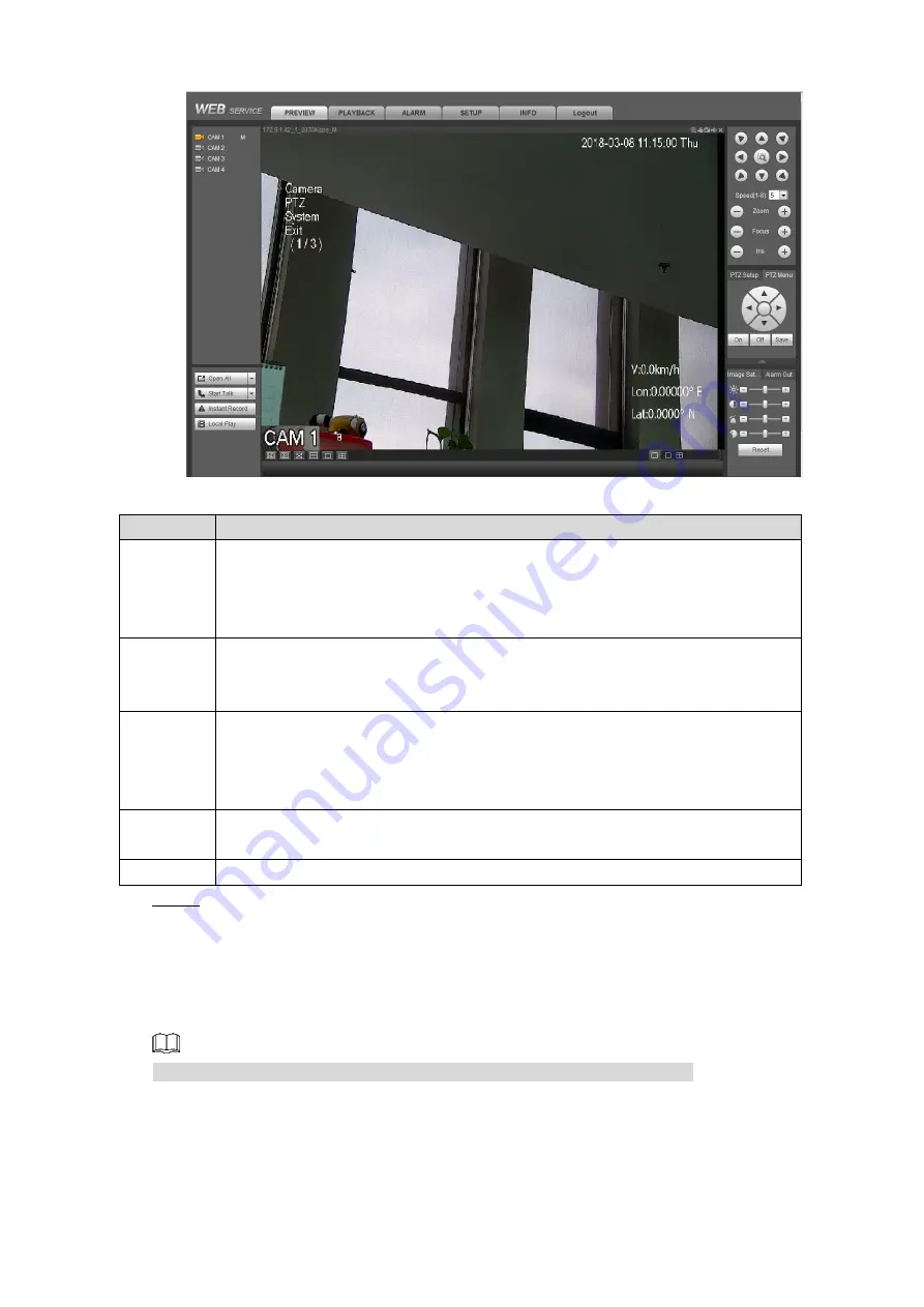
Страница 140: ...pper left corner M represents main stream and S represents sub stream For admin account if you forget password click Forgot password to find back the password For details see 5 3 5 3 3 Reset password Preview Figure 5 5 5 1 3 Configuring IP address Connect the Device to the network and make sure the Device can communicate with other devices in the network diagram Preparation Make sure the Device is...

Страница 141: ...ess which cannot be modified Mode Static Manually enter the IP address subnet mask and gateway DHCP Select the DHCP box the system automatically obtains an IP address When the DHCP function is enabled the IP address gateway and subnet mask cannot be set manually No matter the DHCP function is enabled or not you can view the current IP address IP Address According to your network plan enter the mod...

Страница 142: ... When the HDD is full and there is no extra free disk the recording stops Overwrite When the HDD is full and there is no extra free disk the new recorded video covers the old videos Pack Duration Enter the length of time for each video file The maximum length is 120 minutes Auto Logout Enter the time period for automatic logout if there are no operations during this period In this case you need to...

Страница 143: ...rmat Select a date format Time Format Select a time format System Time Displays the current system date and time Sync PC Click Sync PC to sync the system time with the PC from where you login the web interface System Zone In the Timing Mode list if GPS or NTP is selected configure this parameter Configures the Device time zone DST The DST is applied in some countries or regions Select the DST chec...

Страница 144: ...ce to sync time with the NTP server The maximum value is 65535 minutes Synchronize Port Interval Click Save Step 3 5 1 5 Configuring Remote Devices This section introduces how to add remote devices to Channel 9 Channel 12 5 1 5 1 Initializing the Remote Device Only the initialized remote device can be added If the remote device that you want to add has been initialized please ignore this section P...

Страница 145: ... password setting interface is displayed See Figure 5 10 Password setting Figure 5 10 Configure the password by either of the following two ways Step 5 Select the Using current device password and email info check box then the remote device will use the password and email information of the Device Manually configure password for remote devices 1 Clear the Using current device password and email in...

Страница 146: ...sword and enter it again in the Confirm Password box Click Next The password setting interface is displayed See Figure 5 12 Password protection Figure 5 12 3 Enter the email address if needed Click Next Step 6 The Device starts initializing Device After initialization is completed see Figure 5 13 ...

Страница 147: ...UP CAMERA REMOTE Step 1 The REMOTE interface is displayed Add a remote device Step 2 By search 1 Click Device Search the searched devices are displayed 2 Double click on an IP address or select the check box of a device and then click Add The device displays in the added device area Manual Add 1 Click Manual Add The Manual Add interface is displayed See Figure 5 14 ...

Страница 148: ... remote device The default setting is 554 HTTP Port Enter HTTP Port number of remote device The default setting is 80 Username Enter the user name and password to login the remote device Password Remote Channel Select the channel number that you want to connect Alarm Channel Select a channel from Channel 9 to Channel 12 for the remote device Decode Buffer Enter the size of decode buffer The unit i...

Страница 149: ...ify interface is displayed See Figure 5 15 Modify Figure 5 15 Enter the user name and password of remote device Step 3 The system automatically obtains the user name which is admin by default Enter the IP address of remote device according to your network plan Step 4 Click Save Step 5 After modification the new IP address is displayed in the added device area 5 1 6 Configuring Detect Type After th...

Страница 150: ...u can also enable or disable snapshot function Auto The recording starts automatically according to the record type and recording time as configured in the recording schedule Manual Keep general recording for 24 hours for the selected channel Manual recording operation requires the user have the permission to access STORAGE settings Check to ensure the HDD installed in the Device has been formatte...

Страница 151: ...ted Auto Manual Stop Select the record mode Manual Top priority When the Manual check box is selected the system keeps general recording for 24 hours for the corresponding channel Auto The system starts recording according to the record type such as general alarm motion detect and system alarm and recording time Stop Do not record Enable Stop Enable or disable the scheduled snapshot for the corres...

Страница 152: ... Record schedule Figure 5 18 Configure the parameters For details see Table 5 6 Step 2 Table 5 6 Record schedule parameters description Parameter Description Channel Select a channel to configure the corresponding recording schedule If you configure the same setting for all channels select All Pre record Start recording for 0 seconds to 30 seconds before the alarm event occurs If you enter 0 secon...

Страница 153: ...hannel is recording the current recorded file will be packed and saved according to the new settings On the Record interface you need to select the Schedule check box or the Manual check box for corresponding channel The redundancy HDD works like a backup HDD for recorded videos but it will not back up snapshots Configure the recording time period Step 3 1 Click Setup The Setting interface is disp...

Страница 154: ...ls see 5 1 7 Configuring Record Settings Procedure Select SETUP STORAGE SCHEDULE Snapshot Step 1 The Snapshot interface is displayed see Figure 5 20 Snapshot schedule Figure 5 20 Configuring time period for taking snapshots Step 2 1 Click Setup The Setting interface is displayed See Figure 5 21 Setting Figure 5 21 2 Select the snapshot type and weekday and enter the period for taking snapshot ...

Страница 155: ...on 1 System menu Includes PREVIEW PLAYBACK FACESEARCH ALARM SETUP INFO and Logout 2 Real time monitoring channels For details see 5 2 1 2 Real time Monitoring Channels 3 Voice Talk For details see 5 2 1 3 Voice Talk 4 Instant Record Click Instant Record the record type switches to Manual click again to switch the record type back to Auto This function is only supported by main stream 5 Local playb...

Страница 156: ... 1 5Image and Alarm out Settings 9 Configuring Zero Channel Settings After the Zero Channel Encode function is enabled the displays on the PREVIEW interface Select the split mode if needed For details see 5 2 1 5 3 Configuring Zero Channel Settings For details about enabling Zero Channel Encode function see 5 3 5 1 3 Configuring Zero Channel Settings 5 2 1 2 Real time Monitoring Channels This area...

Страница 157: ...g Click it again to stop recording The recorded files default storage path is C RecordDownload You can modify this path if needed For details see 5 3 1 2 4 Configuring Save Path 7 Snapshot Click this icon to start taking snapshot The snapshots default storage path is C PictureDownload You can modify this path if needed For details see 5 3 1 2 4 Configuring Save Path 8 Audio Turns on off audio If a...

Страница 158: ...ce talk 5 2 1 4 PTZ control panel You can perform the operations through PTZ control panel such as PTZ directions speed zoom focus iris preset tour pattern scan horizontal rotate auxiliary functions light wiper and defrost See Figure 5 27 PTZ movement supports eight directions Speed function controls the movement speed The bigger the value is the faster the movement will be Click to display or hid...

Страница 159: ...escription Channel Select a channel that is connected to PTZ camera Protocol Select the protocol that matches the PTZ camera Address Enter the address for PTZ camera The entered address must be the same with the address configured on the PTZ camera otherwise the PTZ camera cannot be controlled from the Device Baud Rate Select the baud rate for the PTZ camera Data Bit The default value is 8 Stop Bi...

Страница 160: ...ckly move the PTZ camera to the configured presets after configuration 1 In the PTZ Setup list select Preset and then move the camera to the direction that you want to monitor 2 In the Preset box enter the preset value 3 Click Add to complete adding preset 4 In the Preset box enter the preset value and then click Goto the camera moves to the location of preset Click Del to delete the preset Callin...

Страница 161: ...o use this function make sure it is supported on the external device In the PTZ Setup list select Light Click On to turn on the light and click Off to turn off the light Screen Wiper Controls the screen wiper of external device through RS 485 command To use this function make sure it is supported on the external device In the PTZ Setup list select Screen Wiper Click On to turn on the screen wiper ...

Страница 162: ...n Table 5 12 OSD menu parameters description Parameter Description Camera Move the pointer to Camera and then click Save to enter the sub menu of Camera You can configure the camera parameters such as image exposure backlight white balance day night zoom and focus PTZ setting Move the pointer to PTZ and then click Save to enter the sub menu of PTZ You can configure the PTZ parameters such as prese...

Страница 163: ...htness Adjusts the image brightness The bigger the value is the brighter the image will become Contrast Adjusts the image contrast The bigger the value is the more obvious the contrast between the light area and dark area will become Saturation Adjusts the color darkness Adjust the saturation according to the actual situation The bigger the value the lighter the color will become Hue Adjusts the i...

Страница 164: ...multiple channels in the local interface to one channel Then you can view multiple channels from remote access and the network transmission bandwidth can be effectively saved Select a channel and then select the split mode from Then you can view the multiple channel views in one channel See Figure 5 34 Configuring Zero Channel Settings Figure 5 34 5 2 2 Playback interface On the PLAYBACK interface...

Страница 165: ...multi channel view If the playback time of other channels is before the time of the selected channel then other channels will speed up playback till sync with the selected channel If the playback time of other channels is after the time of the selected channel then other channels will pause to wait till sync with the selected channel 5 Record type The alarm type includes Regular MD and Alarm Selec...

Страница 166: ... To use this function the playback should be paused Fast playback and slow playback Move the slider to adjust the playback speed 5 2 2 2 Playing Back Recorded Video Files You can play back recorded video by time or file type During playback the following operations are supported On the channel window click then hold down the left mouse button to select the area you want to enlarge The area is enla...

Страница 167: ... 5 37 File list Figure 5 37 Set the start time and then click the searched recorded files are displayed Step 4 Double click the recorded video file to start playing back recorded video Step 5 Select the video files and then click Download The recorded files default storage path is C RecordDownload You can modify this path if needed Click More to display more settings You can search and download th...

Страница 168: ... folder under the name of RecordDownload Step 4 You can also change the save path if needed The system pops up a message indicating the backing up is in process Step 5 Click to cancel the operation 5 2 2 4 Downloading Recorded Files Click More to display more settings You can search and download the recorded video files by file type or time and verify whether the file is falsified 5 2 2 4 1 Downlo...

Страница 169: ... completed 5 2 2 4 2 Download by Time You can download the recorded video by time Click the Download by Time tab Step 1 The Download by Time interface is displayed See Figure 5 41 Download by time Figure 5 41 Select channel bit stream type start time and end time Step 2 Click Download to Local Step 3 The Download to Local interface is displayed See Figure 5 40 Select the record type and save path ...

Страница 170: ...e verifying progress and result after completed See Figure 5 43 Watermark Figure 5 43 5 2 3 Searching for Face Picture You can search for and download the detected face pictures and play and download the recorded videos corresponding to the pictures Preparation The face detection function is enabled For details see 5 3 3 5 Configuring Face Detection ...

Страница 171: ...ts playing back the recorded videos 10 seconds before and after the time when you captured the face picture For the operations during playback see Table 5 16 Table 5 16 Playback operations Icons Description During playing back click this icon to stop playback When the playback is paused click this icon to start playing back frame by frame During playing back click this icon to stop playback Move t...

Страница 172: ...bled For details see 5 3 3 1 1 Configuring Motion Detect Settings External Alarm The alarm is triggered by the alarm signal that is detected by the alarm input port on the Device The local alarm function is enabled For details see 5 3 3 2 Configuring Alarm Input Settings Tampering The alarm is triggered when the camera lens is covered The tampering function is enabled For details see 5 3 3 1 3 Con...

Страница 173: ...x Step 3 If the system displays the ALARM tab when the selected alarm type is triggered the displays on the ALARM tab and the system automatically records the alarm information Click the ALARM tab to clear the icon If the system displays the ALARM tab when the selected alarm type is triggered the alarm information displays in the table on the right side of the ALARM tab interface In the Alarm Soun...

Страница 174: ...then enter the time in the box Saturation Adjusts the color darkness Adjust the saturation according to the actual situation The bigger the value the lighter the color will become Brightness Adjusts the image brightness through linear mode The bigger the value is the brighter the image will become Contrast Adjusts the image contrast The bigger the value is the more obvious the contrast between the...

Страница 175: ...uring Encode Parameters 5 3 1 2 1 Configuring Encode Setting You can configure the encode settings for main stream and sub stream Select SETUP CAMERA ENCODE Encode Step 1 The Encode interface is displayed see Figure 5 48 Encode setting parameters might be different depending on the model you purchased and the actual product shall prevail Encode settings Figure 5 48 Select a channel Step 2 Configur...

Страница 176: ...itoring environment But the maximum bit rate value changes around the configured value Select Customized you can manually enter Bit Rate information in the box Image Quality This function is available if you select VBR in the Bit Rate list Select the image quality level The higher the value the better the image will become Reference Bit Rate The system recommends the optimal bit rate range accordi...

Страница 177: ...lect a resolution according to your actual situation If a channel between Channel 9 and Channel 12 is selected the resolution is the same with the main stream and cannot be modified Image Quality Configures the image quality by 6 levels The higher the level the better the image will become Interval Time interval for taking a snapshot Select Customized to configure the snapshot frequency for manual...

Страница 178: ...d area is invisible when output to VGA monitor or small screen but visible when output to web or during recording Maximum four covered areas can be set Time Display Select the Time Display check box the Setup button is displayed Then click Setup the time is displayed on the channel window and then drag it to a proper location Channel Display Select the Channel Display check box the Setup button is...

Страница 179: ...guring Channel Name You can configure the channel name for the corresponding camera Select SETUP CAMERA CAM NAME Step 1 The Chaneel Name interface is displayed See Figure 5 52 Channel Name Figure 5 52 Configure channel name Step 2 For Channel 1 and Channel 8 modify the channel name if needed For Channel 9 to Channel 12 if there are remote cameras are connected the name of remote camera displays on...

Страница 180: ...rvice port The default setting is 37777 UDP Port User Datagram Protocol The default value setting is 37778 You can enter the value according to your actual situation HTTP Port Hyper Text Transfer Protocol port The default setting is 80 You can enter the value according to your actual situation and in this case please add the modified value after the address when logging the Device on the browser H...

Страница 181: ...rt The default setting is 554 If the default setting is displayed you do not need to configure this parameter Channel Numbers from 1 For example if it is channel 2 then enter channel 2 Subtype stream type The main stream is 0 subtype 0 the sub stream is 1 subtype 1 For example when you want to get the sub stream of channel 2 from a device refer to the following URL format rtsp admin admin_123 192 ...

Страница 182: ... certificate Figure 5 55 Enter the information for the parameters such as Country State and Location Step 3 In the IP or Domain Name box enter the same value with that of Device Click Create Step 4 The system pops up a message after the creating is succeeded Downloading Root Certificate For the first time to use HTTPS after changing the PC you need to download root certificate Select SETUP NETWORK...

Страница 183: ...nload by file Figure 5 56 Click Open Step 3 The Certificate interface is displayed See Figure 5 57 Certificate Figure 5 57 Click Install Certificate Step 4 The Certificate Import Wizard interface is displayed See Figure 5 58 ...

Страница 184: ...import wizard Figure 5 58 Click Next Step 5 The certificate store selection interface is displayed See Figure 5 59 Certificate store Figure 5 59 Click Next Step 6 The certificate import completing wizard is displayed See Figure 5 60 ...

Страница 185: ...certificate or download root certificate you need to set the HTTPS port Select SETUP NETWORK CONNECTION Connection Setting Step 1 The Connection Setting interface is displayed See Figure 5 61 Connection setting HTTPS port Figure 5 61 Enter HTTPS port number The default setting is 443 Step 2 Click Save Step 3 Logging through HTTPS Open the browser enter https xx xx xx xx port the login interface is...

Страница 186: ...WIFI Step 1 The WIFI interface is displayed In the Working Mode Collection list select Mac Step 2 The Mac setting interface is displayed See Figure 5 62 Mac setting Figure 5 62 In the Upload Interval box enter the interval Step 3 Configure this parameter when the Device is accessed to Platform Click Save Step 4 5 3 2 2 2 Viewing MAC Information After the MAC information has been collected you can ...

Страница 187: ... by the DDNS service provider to register the information such as domain from PC located in the WAN After you have registered and logged in the DDNS website successfully you can view the information of all the connected devices under this user name Procedure Select SETUP NETWORK DDNS Step 1 The DDNS interface is displayed See Figure 5 64 DDNS Figure 5 64 Select the Enable check box Step 2 Select a...

Страница 188: ...he domain name and then press Enter key If the web interface is displayed the configuration is successful 5 3 2 4 Configuring Email Settings You can configure the email settings to enable the system to send the email as a notification when there is an alarm event occurs such as video detection and system events Select SETUP NETWORK EMAIL Step 1 The Email interface is displayed See Figure 5 65 Emai...

Страница 189: ...id the large amount of emails caused by frequent alarm events Health Enable The system can send a test email to check the connection Select the Health Enable check box and then enter the interval The system can send a test email to check the connection according to the interval The value ranges from 30 minutes to 1440 minutes Email Test Click Test to test the email sending and receiving function I...

Страница 190: ...he mailbox must have applied SMTP service NONE 25 126 smtp 126 com NONE 25 The mailbox must have applied SMTP service Click Save Step 4 5 3 2 5 Configuring FTP Settings You can store the recorded videos and snapshots on the FTP server Preparation Make sure you have purchased or download a FTP server and installed it on your PC For the created FTP user you need to set the write permission otherwise...

Страница 191: ...er on FTP server If you do not enter the name of remote directory the system automatically creates the folders according to the IP time and channel If you enter the name of remote directory the system creates the folder with the entered name under the FTP root directory first and then automatically creates the folders according to the IP time and channel File Length Enter the length of the uploade...

Страница 192: ...type Alarm MD and General that you want to upload The selected record type will be uploaded during the configured time period Time Period FTP Test Click FTP Test to check if the setting is successful The system pops up a message to indicate success or failure If failed please check the network connection or configurations Click Save Step 4 5 3 2 6 Configuring P2P Settings P2P is a private network ...

Страница 193: ...configuration is completed in the Status box of the P2P interface it shows Online which means the device registration is succeeded Adding Device into Mobile Phone Client To use this function take adding device into mobile phone client as an example On your mobile phone download the application Step 1 Open the application Step 2 Add a device Step 3 1 Click and then select Device Manager The Device ...

Страница 194: ...through 3G 4G network or Wi Fi Make sure the Device can communicate with other devices in the network diagram The Device can also work as a hotspot to share the network connection to other terminals If both 3G 4G and Wi Fi are available the Device connects to Wi Fi and disconnected from 3G 4G 5 3 2 7 1 Configuring 3G 4G Settings Preparation Make sure the Device is equipped with 3G 4G module and in...

Страница 195: ...e enter user name and password then the Device is automatically accessed to private network 3G Type Displays 3G 4G network type which is used to distinguish the 3G 4G modules among Communication Operators such as TD LTE APN Displays access point of Communication Operator If you select Customized manually enter the APN information in the box AUTH Authentication mode includes three protocols PAP CHA...

Страница 196: ...iguring Wi Fi Network You can connect the Device to network through Wi Fi Then connect PC to the same network to login web interface of Device This function is supported on the Device with Wi Fi module Preparation Make sure the Device is connected to Wi Fi Procedure Select SETUP NETWORK WIFI Step 1 The WIFI interface is displayed In the Working Mode Selection list select Wifi Step 2 The Wi Fi inte...

Страница 197: ...ystem will automatically obtain the IP address subnet mask and gateway 3 Click Save Click Save Step 4 Click Refresh to refresh the connection status After connection is succeeded you can view the current hotspot IP address subnet mask and gateway in the WIFI Working Info area 5 3 2 7 3 Configuring Wi Fi Hotspot The Device can work as a hotspot to share the network connection to other terminals The...

Страница 198: ...location to the specified server which acts as the transit to make it easier for the Client software to access the Device Select SETUP NETWORK REGISTER Step 1 The REGISTER interface is displayed See Figure 5 73 Register Figure 5 73 Select the Enable check box Selected by default Step 2 Configure the parameters For details see Table 5 28 Step 3 Table 5 28 Register settings parameters description Pa...

Страница 199: ... Detect Settings When the moving object appears and moves fast enough to reach the preset sensitivity value the system activates alarm Select SETUP EVENT DETECT Motion Detect Step 1 The Motion Detect interface is displayed see Figure 5 74 Motion Detect Figure 5 74 Select the Enable check box and the channel that you want to apply the motion detect Step 2 function Set motion detect region Step 3 1 ...

Страница 200: ...cord Channel check box and select a record channel s when an alarm event occurs the corresponding channel starts recording automatically The recording setting for alarm must be configured beforehand The motion detect recording is enabled For details see 5 1 8 Configuring Recording Schedule The auto recording is enabled For details see 5 1 7 Configuring Record Settings Delay Set a length of time fo...

Страница 201: ...t Settings Show Message Select the Show Message check box to enable a pop up message in your local host PC when an alarm event occurs Send Email Select the Send Email check box to enable the system to send an email notification when an alarm event occurs To use this function make sure the email function is enabled For details see 5 3 2 4 Configuring Email Settings Buzzer Select the Buzzer check bo...

Страница 202: ...e video is displayed in a single color because of the causes such as sunlight status the monitoring cannot be continued normally and in this case the system activates alarm and links the configured actions Select SETUP EVENT DETECT Tampering Step 1 The Tampering interface is displayed see Figure 5 77 Tampering Figure 5 77 Select the Enable check box and the channel that you want to apply the tampe...

Страница 203: ...om Channel 9 to Channel 12 Configure the parameters For details see Table 5 30 Step 4 Table 5 30 Alarm parameters description Parameter Description Alarm Name Enter a customized alarm name Overlay Select the Overlay check box the alarm name will display on the channel window Anti dither Enter event detection lasting time The system records only one event during this period Type If Local Alarm is s...

Страница 204: ...he selected channels is displayed on the Device local interface Configure the tour interval and other settings according to your actual need For details see 4 2 1 4 2 Configuring Tour Settings After tour is completed the live view screen stays on the current image of tour Snapshot Select the Snapshot check box and select a snapshot channel s When an alarm event occurs the corresponding channel sta...

Страница 205: ... actual interface shall prevail Attempt s If Illegal Login is selected configure this parameter In the Attempt s box enter the maximum number of allowed password input errors If the number of password input errors reaches this value the user account will be locked Lock Time If Illegal Login is selected configure this parameter If the number of password input errors reaches this value the user acco...

Страница 206: ...eled Show Message Select the Show Message check box to enable a pop up message in your local host PC when an alarm event occurs Snapshot Select the Snapshot check box and select a snapshot channel s When an alarm event occurs the corresponding channel starts capturing automatically You can also configure the frequency size and quality of snapshot For details see 4 3 1 2 3 Configuring Snapshot Sett...

Страница 207: ...nding alarm output port never generate alarm Click Save Step 3 Status Indicates the status of each alarm output port indicates there is alarm output and indicates there is no alarm output 5 3 3 5 Configuring Face Detection You can enable the face detection function for Channel 9 to Channel 12 The system automatically detects the faces and takes snapshots for the corresponding channel Select SETUP ...

Страница 208: ...disk if needed The customized disk can only be used to store the multi channel view recorded files For details about enabling multi channel recording see 5 3 5 1 3 Configuring Zero Channel Settings Storage Device Figure 5 82 When you select an HDD you can format it if needed Please operate with care 5 3 4 2 Viewing HDD Information You can view the HDD information time period of recorded video file...

Страница 209: ...gs here will not affect the recording and playback display effect Select SETUP SYSTEM DISPLAY Display Step 1 The Display interface is displayed See Figure 5 85 Display Figure 5 85 Configure the parameters For details see Table 5 32 Step 2 Table 5 32 Basic display setting parameters description Parameter Description Resolution Select a resolution for the display The settings take effect after reboo...

Страница 210: ...oup Optimization Alarm tour Motion tour General tour Select SETUP SYSTEM DISPLAY Tour Step 1 The Tour interface is displayed see Figure 5 86 Tour Figure 5 86 Select the Enable check box Step 2 Configure the parameters For details see Table 5 33 Step 3 Table 5 33 Tour settings parameters description Parameter Description Interval Configure the time for the channel groups display in turn The default...

Страница 211: ...ession resolution and frame rate The recorded video files are saved in the customized HDD which if full the files will overwrite the old ones automatically SD card is regarded as customized storage disk and you can also set HDD as customized disk For details see 5 3 4 1 Managing Storage Device Select SETUP SYSTEM DISPLAY Zero Ch Encode Step 1 The Zero Ch Encode interface is displayed See Figure 5 ...

Страница 212: ... DISPLAY Preview Overlay Step 1 The Preview Overlay interface is displayed See Figure 5 88 Preview overlay Figure 5 88 Configure the parameters For details see Table 5 35 Step 2 Table 5 35 Preview overlay setting parameters description Parameter Description Time Display Select the Time Display check box the Setup button is displayed Then click Setup the time is displayed on the channel window and ...

Страница 213: ...n Horizontal The left and right side of channel screen are reversed Vertical The channel screen is displayed upside down Click Save Step 4 5 3 5 2 Configuring RS 232 Port Parameters You can configure the RS 232 serial port parameters such as baud rate date bits stop bits and parity Select SETUP SYSTEM RS232 Step 1 The RS232 interface is displayed See Figure 5 90 RS 232 settings Figure 5 90 Configu...

Страница 214: ...op Bit Select a stop bit The options include 1 1 5 and 2 Parity Select a parity mode from None Odd Even Mark and Null Click Save Step 3 5 3 5 3 Managing User Account You can add modify and delete user accounts and groups and configure security questions for admin account The Default User and Authority The default user account is admin The admin account is defined as the high privileged user To man...

Страница 215: ...up Adding a user Select SETUP SYSTEM ACCOUNT User Step 1 The User interface is displayed See Figure 5 91 User Figure 5 91 Click Add User Step 2 The Add User interface is displayed See Figure 5 92 Add user Figure 5 92 Configure the parameters For details see Table 5 38 Step 3 Table 5 38 Parameters description for adding user ...

Страница 216: ... login the Device Authority Select the authorities to the user of a group The authority for admin account cannot be changed To management account easily when defining the user account authority it is recommended not to give the authority to the common user account lower than the advanced user account Authority Click Save Step 4 Click to modify user information click to delete the user Modifying Pa...

Страница 217: ... 5 3 3 Reset password Click Save Step 4 The new password can be set from 8 characters through 32 characters and contains at least two types from number letter and special characters excluding Please enter a strong password according to the password strength indication The user with Account authority can also modify the password of other users 5 3 5 3 2 Group Management You can perform the operatio...

Страница 218: ...ave Step 5 Click to modify the corresponding group information click to delete the group 5 3 5 3 3 Reset password Open a browser and login the web interface of Device Step 1 The login interface is displayed In the Username box enter admin Step 2 The Forgot password string is displayed See Figure 5 96 Login Figure 5 96 Click Forgot password Step 3 The Reset the password is displayed See Figure 5 97...

Страница 219: ...times will cause the admin account locked for five minutes In the security code box enter the security code received in your reserved email box Step 5 Click Next Step 6 The new password setting interface is displayed See Figure 5 98 New password setting Figure 5 98 In the New Password box enter the new password and enter it again in the Confirm Step 7 Password box The new password can be set from ...

Страница 220: ... ONLINEUSER the Online User interface is displayed See Figure 5 99 Online user Figure 5 99 5 3 6 Configuring Vehicle Settings 5 3 6 1 Configuring Speed Select SETUP VEHICLE SPEED Step 1 The SPEED interface is displayed see Figure 5 100 Speed Figure 5 100 Configure the parameters For details see Table 5 39 Step 2 Table 5 39 Speed parameters description Parameter Description Speed Ratio The paramete...

Страница 221: ...stem Priority use of the speed information from vehicle pulse 1 Pulse 1 Displays the frequency of pulse system from the accessed device Pulse 2 Click Save Step 3 5 3 6 2 Configuring Sensor Select SETUP VEHICLE SENSOR Step 1 The G SENSOR interface is displayed See Figure 5 101 G SENSOR Figure 5 101 Adjust the type of side shaft and slope angle according to the device installation angle Step 2 Click...

Страница 222: ...us is off the system report the position to platform according to the configured report interval Platform schedule In the Report Strategy list select Platform Schedule The Platform Schedule setting interface is displayed See Figure 5 103 The platform obtains the device position by the configured schedule The schedule is configured at the Platform For details see the manual of platform Position rep...

Страница 223: ...y Upgrade firmware timely 5 4 2 Viewing System Information 5 4 2 1 Viewing Version Details You can view the Device version information Select INFO INFO VERSION The VERSION interface is displayed See Figure 5 104 Version details Figure 5 104 5 4 2 2 Viewing System Logs You can search view and back up the system logs to PC Select INFO INFO LOG Step 1 The Log interface is displayed See Figure 5 105 ...

Страница 224: ...tude and search results Select INFO INFO SATELLITE INFO The SATELLITE INFO interface is displayed See Figure 5 106 Click Refresh to display the latest satellite information If the GPS module state indicates Normal and not positioned within five minutes the GPS module will automatically reset and re position When the positioning information is obtained again the GPS module reset times is up to 20 o...

Страница 225: ...ing old files auto booting up auto shutdown and delay for auto shutdown 5 4 3 1 Auto Reboot After configuring auto reboot when the Device is working it reboots according to the schedule Select SETUP SYSTEM MAINTAIN Step 1 The Auto Maintain interface is displayed See Figure 5 107 Automatic maintenance Figure 5 107 Select the auto reboot time Step 2 Click Save Step 3 ...

Страница 226: ... to the ACC power off time and auto boot up setting If you have set the time auto boot up there are two situations when the ACC is powered off If the system time is between the auto boots up and auto shutdown the Device is turned off by the configured time If the system time is before the auto booting up or after the auto shutdown the Device is turned off immediately If the auto booting up is not ...

Страница 227: ...tep 2 The system starts backing up configurations 5 4 4 2 Restoring Configurations You can use the backed up configurations to quickly configure the Device and restore the device configurations Select SETUP SYSTEM IMP EXP Step 1 The Import Export interface is displayed See Figure 5 109 Importing and exporting configurations Figure 5 109 Click Browse and then select the backup configuration file th...

Страница 228: ...ed except the IPV4 address information all the other configurations will return to the default and the Device requires initialization again in next rebooting Please operate with caution When there is a user operating on the local interface the factory default settings cannot be performed until the local user log out 5 4 5 Upgrading System Firmware You can import the upgrading file to upgrade the s...

Страница 229: ...n the web is connected to the external storage device Procedure Select INFO INFO NETWORK SNIFFER Step 1 The NETWORK SNIFFER interface is displayed see Figure 5 112 Network packet capturing Figure 5 112 Select the Ethernet card and save path Step 2 Select the Target Filter check box and then enter the IP address that you want to filter Step 3 Click Start Step 4 The system starts capturing packet Cl...

Страница 230: ...Mouse Operations 219 6 Logging the Device from DSS Beside from web you can also remotely login the Device from Digital Surveillance System DSS For details see the manual of DSS ...

Страница 231: ...led b Input voltage is not stable or too low c The Device is not properly installed which result in poor contact between components d Poor heat dissipation and too many dusts result in poor working environment for the Device e Hardware malfunction 3 Q HDD cannot be detected after rebooting A There are the following possibilities a No HDD is installed b Poor HDD box contact c HDD is damaged 4 Q No ...

Страница 232: ...ing possibilities a Video quality setting is too low b Program read error bit data is too small and there is full of mosaic in the screen Please firstly try to restart the DVR to solve this problem c HDD Error d Hardware malfunction 8 Q No audio A There are the following possibilities a It is not an active speaker b Audio cable is damaged c Audio function of sub stream is not enabled during remote...

Страница 233: ...2 Q Cannot login Client or web A There are the following possibilities a ActiveX plugin is blocked b Dx8 1 or above is not installed c Network connection error d Network setting error e User name and password are not correct f Client version is not compatible with NVR program 13 Q There is mosaic or no image when previewing or playing back video file on the web A There are the following possibilit...

Страница 234: ...ery has run out of power e Remote control is damaged or Device front panel is damaged 18 Q Record storage time is not enough A There are the following possibilities a Low camera quality dirty lens camera installed against the light or iris not properly adjusted caused large big rate b HDD capacity is not enough c HDD is damaged 19 Q Cannot play the downloaded file A There are the following possibi...

Страница 235: ...card package is not enabled 21 Q Cannot connect to DSS platform A There are the following possibilities a 3G 4G dial up failed b The device is not added to the platform c The auto register settings on the Device are not configured d The auto register setting parameters between platform and Device do not match ...

Страница 236: ...to the USB port of the Device Operation Function Click click the left mouse button If the user has not logged in the system the password box is displayed first During real time monitoring click the left mouse button to enter the main menu When you have selected one menu item click it to view menu content Implement the operation indicated on the control Change the status of the check box Click the ...

Страница 237: ...rs for example press 1 means entering You can also directly use the mouse to click to enter the characters If you want to enter Chinese the Chinese pinyin can also be entered by the Device front panel or soft panel For example enter Chinese pinyin zhong all the Chinese that might satisfy the input are displayed in the box You can press the arrow keys to move up and down to search the correct word ...

Страница 238: ...nd main menu To use PTZ control and color setting click in the channel that you want to configure these two settings If the current screen is in multi window mode it will switch to the single window of the corresponding channel Do not save the setting and exit the current menu Wheel button In numeral input box rotate the wheel button to increase or decrease numeral value Switch the items in the co...

Страница 239: ...l capacity M Channel number Demand time length hour HDD capacity occupied per hour M hour Recording time calculation formula Recording time hour HDD total capacity M HDD capacity occupied per hour M hour Channel number The video recorder adopts MPEG4 H 264 compression technology which fluctuates greatly Therefore when calculating HDD capacity you should accord to the bit rate to calculate the file...

Отзывы: