144
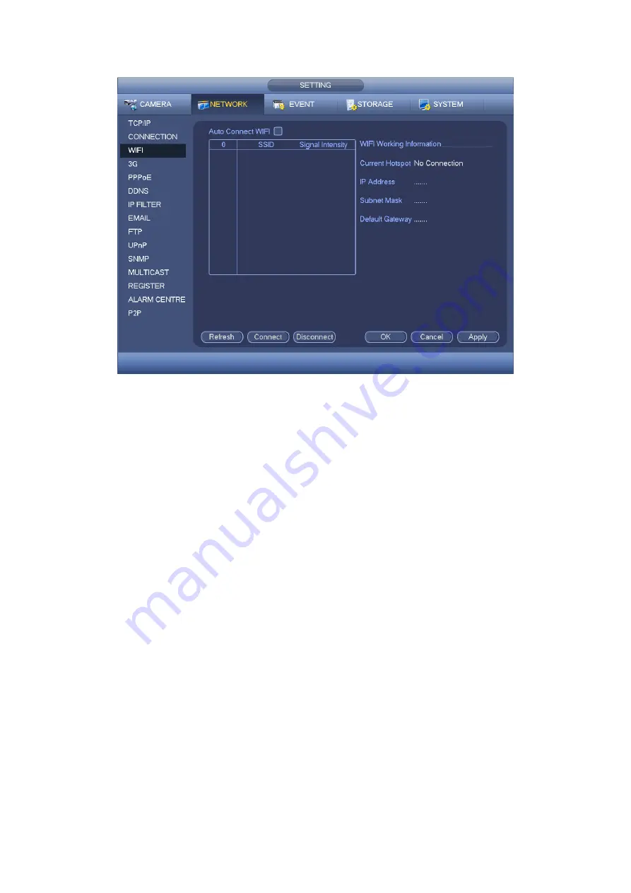
Figure 4-86
WIFI working status: Here you can view current connection status.
Please note:
After successful connection, you can see WIFI connection icon at the top right corner
of the preview interface.
When the hotspot verification type is WEP, system displays as AUTO since the device
can not detect its encryption type.
System does not support verification type WPA and WPA2. The display may become
abnormal for the verification type and encryption type.
After device successfully connected to the WIFI, you can view the hotspot name, IP
address, subnet mask, default gateway and etc.
4.11.2.4 3G
3G setup interface is shown as below. See Figure 4-87.
Please refer to the following contents for the parameter information.
Pane 1: Display 3G signal intensity after you enabled 3G function.
Pane 2: Display 3G module configuration information after you enabled 3G function.
Pane 3: Display 3G module status information after you enabled 3G function.
It is to display current wireless network signal intensity such as EVDO, CDMA1x, WCDMA,
WCDMA, EDGE and etc.
3G module: It is to display current wireless network adapter name.
3G Enable/Disable: Check the box here to enable 3G module.
Network type: There are various network types for different 3G network modules. You
can select according to your requirements.
Содержание HDCVI series
Страница 1: ...Dahua HDCVI Standalone DVR User s Manual Dahua HDCVI Standalone DVR User s Manual V1 6 1 ...
Страница 172: ...162 Figure 4 104 Figure 4 105 ...
Страница 173: ...163 Figure 4 106 Figure 4 107 ...
Страница 189: ...179 Figure 4 124 Figure 4 125 ...
Страница 190: ...180 Figure 4 126 Figure 4 127 ...
Страница 191: ...181 Figure 4 128 Figure 4 129 ...
Страница 194: ...184 Figure 4 133 Figure 4 134 ...
Страница 201: ...191 Figure 4 144 Figure 4 145 4 11 4 1 2 2Trigger Snapshot ...
Страница 203: ...193 Figure 4 147 Figure 4 148 4 11 4 1 2 3Priority ...
Страница 220: ...210 Figure 4 169 For digital channel the interface is shown as below See Figure 4 170 Figure 4 170 4 11 5 6 ATM POS ...
Страница 234: ...224 Figure 4 187 ...
Страница 252: ...242 Figure 5 26 5 8 2 Network 5 8 2 1 TCP IP The single Ethernet port interface is shown as in Figure 5 27 Figure 5 27 ...
Страница 269: ...259 Figure 5 55 Figure 5 56 ...
Страница 282: ...272 Figure 5 71 Figure 5 72 ...
Страница 289: ...279 Figure 5 81 Figure 5 82 Figure 5 83 Please refer to the following sheet for detailed information ...
Страница 332: ...322 448K 196M 512K 225M 640K 281M 768K 337M 896K 393M 1024K 450M 1280K 562M 1536K 675M 1792K 787M 2048K 900M ...


