User’s Manual
47
◇
FORCED ARM
: Select
YES
or
NO
.
If
YES
is selected, the key zone will be armed even though there are open zones. If
NO
is
selected, the arming will take place only if all the area zones are ready for arming.
◇
Link: Set link output associated with the input.
●
SPECIAL
If the
SPECIAL
option is selected, two submenus are proposed.
◇
RESTART
: This option turns off and immediately re-arms the controller. This function can be
useful to perform
PATROL ROUND
to disarm one or more areas getting automatic re-arm
after the programmed exit time area.
◇
TIMER OFF
: This option is not subject to
TRIGGER
,
DELAY OR FORCED
and works only in the
table step from
N.C.
to
N.O.
status. When opened, it locks arming operations subject to a
TMER which are programmed for the AREAS to which it is associated. In practice, it functions
as a key to lock/unlock
ON/OFF TIMERS
active on the
AREAS
.
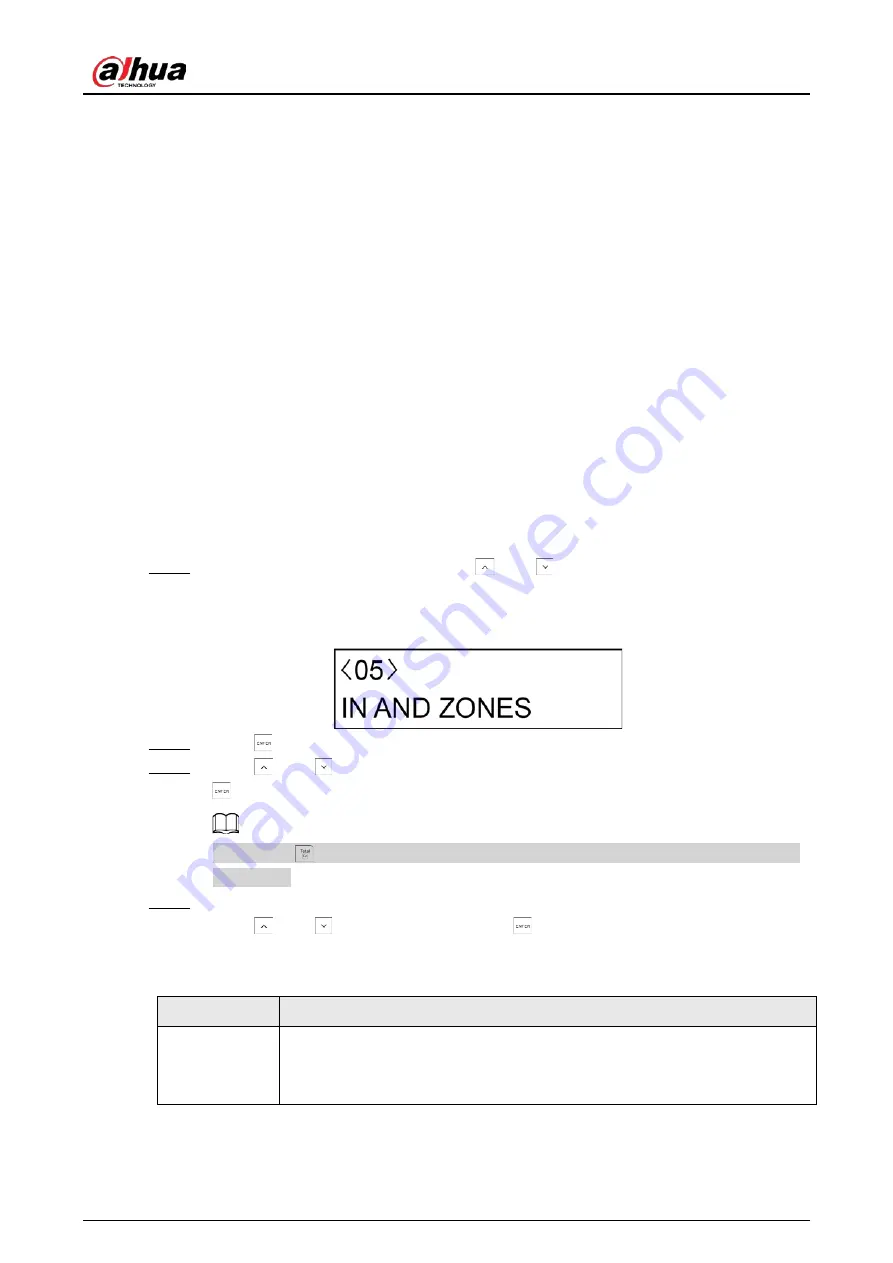
7.8 In and Zones
You can set maximum eight
IN AND ZONES
couples. For each
IN AND ZONES
, you can combine two
zones and establish the alarm linkage between them.
Step 1
After entering the installer menu, press
and
to scroll up and down until you reach
the
IN AND ZONES
menu.
Figure 7-7 In and zones
Step 2
Press
to enter the programming mode.
Step 3
Press
and
to select the
IN AND ZONE
that you want to configure, and then press
.
By pressing
+ 2, you can enter the
EDITING
mode for changing the description of
IN
AND ZONE
.
Step 4
Configure the parameters.
Press
and
to alter the options. Press
to confirm the setting and move to the
next submenu.
Table 7-4 IN AND ZONE programming settings
Submenu
Setting
STATUS
●
ACTIVE
: This
IN AND ZONE
is enabled.
●
ISOLATE
: This
IN AND ZONE
is programed but not used.
●
OFF
: This
IN AND ZONE
is disabled.
Содержание DHI-ARC3008C
Страница 1: ...Alarm Controller User s Manual ZHEJIANG DAHUA VISION TECHNOLOGY CO LTD V2 0 1...
Страница 25: ...User s Manual 14 2 4 Wiring Figure 2 6 Wiring Figure 2 7 Wiring of detectors...
Страница 31: ...User s Manual 20 4 3 Wiring Figure 4 3 keypad connection...
Страница 41: ...User s Manual 30 5 2 Wiring Figure 5 2 Wiring of detectors...
Страница 45: ...User s Manual 34 Figure 6 2 Remove plugs Step 2 Attach the thermal pad to the 4G module...
Страница 137: ...User s Manual...


