background image


2 Port and Indicator 

2.1 Front Panel 

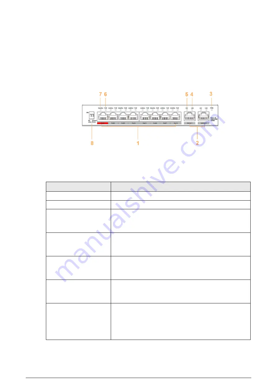
The following figure is for reference only, and might differ from the actual product. 

Figure 2-1 Front panel 


The following are all the ports and indicators on the front panel of the 4/8-port unmanaged desktop 
switch. The actual device may only have a part of them. Refer to the table below for the contents of 
the actual device panel. 

Table 2-1 Description of front panel 

No. 

Description 

10/100 Mbps or 10/100/1000 Mbps self-adaptive Ethernet ports 

10/100 Mbps or 10/100/1000 Mbps self-adaptive uplink port 

Power indicator 

  On: Power on 

  Off: Power off 

Single-port connection status indicator (Link) 

  On: Connected to device 

  Off: Not connected to device 

Single-port data transmission status indicator (Act) 

  Flashes: Data transmission is in progress 

  Off: No data transmission 

PoE port status Indicator 

  On: Powered by PoE 

  Off: Not powered by PoE 

Single-port connection or data transmission status indicator 
(Link/Act) 

  On: Connected to device 

  Off: Not connected to device 

  Flashes: Data transmission is in progress 

Содержание DH-PFS3006-4GT-60

Страница 1: ...Ethernet Switch 4 8 port Unmanaged Desktop Switch Quick Start Guide V1 0 0...

Страница 2: ...e actual product shall prevail We are not liable for any loss caused by the operations that do not comply with the manual The manual would be updated according to the latest laws and regulations of re...

Страница 3: ...II when using the device If there is any uncertainty or controversy please refer to our final explanation...

Страница 4: ...ge Do not disassemble the device without professional instruction Transport use and store the device in allowed ranges of humidity and temperature When removing the cable power off the device first to...

Страница 5: ...atures 1 2 Port and Indicator 2 2 1 Front Panel 2 2 2 Rear Panel 3 3 Installation 4 3 1 Preparation 4 3 2 Desktop Mount 4 3 3 Wall Mount 4 4 Wiring 5 4 1 Connecting GND 5 4 2 Connecting Power Cord 5 4...

Страница 6: ...for different scenarios The device also supports power consumption management which can adapt to the fluctuation of power consumption of terminal device to ensure stable operation The device is applic...

Страница 7: ...n 1 10 100 Mbps or 10 100 1000 Mbps self adaptive Ethernet ports 2 10 100 Mbps or 10 100 1000 Mbps self adaptive uplink port 3 Power indicator On Power on Off Power off 4 Single port connection status...

Страница 8: ...Extend Mode Extends the maximum transmission distance to 250 m but reduces average transmission speed to 10 Mbps Speed Not included in the figure Uplink port speed indicator On 100 Mbps 1000 Mbps Off...

Страница 9: ...solid and flat desktop 3 3 Wall Mount Step 1 Drill two M4 screws into the wall leaving a space of 4 mm between the wall and the head of the screw Screws do not come with the package Purchase them as n...

Страница 10: ...ground cable to the ground bar turn the hex nut clockwise with a wrench to fasten the other end of the ground cable to the ground terminal Figure 4 1 Connect GND 4 2 Connecting Power Cord Before conne...

Страница 11: ...n white 8 brown 4 4 Connecting PoE Ethernet Port You can directly connect the device PoE Ethernet port to the switch PoE Ethernet port through network cable to achieve synchronized network connection...

Страница 12: ...We suggest that you download and use the latest version of client software Nice to have recommendations to improve your device network security 1 Physical Protection We suggest that you perform physic...

Страница 13: ...inder encrypted transmission will cause some loss in transmission efficiency 11 Secure Auditing Check online users we suggest that you check online users regularly to see if the device is logged in wi...

Отзывы: