Dahua DH-HAC-HFW1200T-A Скачать руководство пользователя страница 2

Foreword    I 


Foreword 

General 

This  user’s  manual  (hereinafter  referred  to  be  "the  Manual")  introduces  the  functions, 
installation, and operations of the camera. 

Safety Instructions 

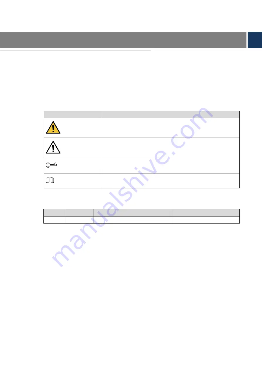
The following categorized signal words with defined meaning might appear in the Manual. 

Signal Words 

Meaning 

WARNING


Indicates a medium or low potential hazard which, if not avoided, 

could result in slight or moderate injury. 

CAUTION


Indicates  a  potential  risk  which,  if  not  avoided,  could  result  in 

property damage, data loss, lower performance, or unpredictable 

result. 

TIPS


Provides methods to help you solve a problem or save you time. 

NOTE


Provides additional information as the emphasis and supplement 

to the text. 

Revision History 

No. 

Version 

Revision Content 

Release Time 

V1.0.0 

First Release. 

June 8, 2018 

Privacy Protection Notice 

As the device user or data controller, you might collect personal data of others' such as face, 

fingerprints, car plate number, Email address, phone number, GPS and so on. You need to be 

in  compliance  with  the  local  privacy  protection  laws  and  regulations  to  protect  the  legitimate 

rights  and  interests  of  other  people  by  implementing  measures  include  but  not  limited  to: 

providing  clear  and  visible  identification  to  inform  data  subject  the  existence  of  surveillance 

area and providing related contact. 

About the Manual 


The  Manual  is  for  reference  only.  If  there  is  inconsistency  between  the  Manual  and  the 

actual product, the actual product shall prevail. 


We are not liable for any loss caused by the operations that do not comply with the Manual. 


The  Manual  would  be  updated  according  to  the  latest  laws  and  regulations  of  related 

regions. For detailed information, see the paper manual, CD-ROM, QR code or our official 

Содержание DH-HAC-HFW1200T-A

Страница 1: ...HDCVI Bullet Camera Lite User s Manual V1 0 0...

Страница 2: ...t Release June 8 2018 Privacy Protection Notice As the device user or data controller you might collect personal data of others such as face fingerprints car plate number Email address phone number GP...

Страница 3: ...ill might be deviation in technical data functions and operations description or errors in print If there is any doubt or dispute please refer to our final explanation Upgrade the reader software or t...

Страница 4: ...y or responsibility for all the fires or electrical shock caused by improper handling or installation Environment Do not aim the device at strong light to focus such as lamp light and sun light Transp...

Страница 5: ...rwise it might damage the device When the camera is in the condition of PoC power supply do not connect any other device between the camera and PoC transceiver including UTC Balun optical transceiver...

Страница 6: ...imits are designed to provide reasonable protection against harmful interference in a commercial environment Operation of this equipment in a residential area is likely to cause harmful interference i...

Страница 7: ...7 3 3 Installing Model C 8 3 4 Installing Model D 9 3 5 Installing Model E 10 3 6 Installing Model F 11 3 7 Installing Model G 12 3 8 Installing Model H 13 3 9 Installing Model I 1 and Model I 2 14 3...

Страница 8: ...able to cover the high definition monitoring needs for locations with low ambient light including road warehouse underground parking lot bar pipeline and gas station Features 1 2 720p series support o...

Страница 9: ...Design 2 2 Design Dimension 2 1 Model A 1 mm in Figure 2 1 Model A 2 mm in Figure 2 2 Model B mm in Figure 2 3 Model C mm in Figure 2 4 Model D mm in Figure 2 5...

Страница 10: ...Design 3 Model E mm in Figure 2 6 Model F mm in Figure 2 7 Model G mm in Figure 2 8 Model H mm in Figure 2 9 Model I 1 mm in Figure 2 10 Model I 2 mm in Figure 2 11...

Страница 11: ...gn 4 Model J mm in Figure 2 12 Model K 1 mm in Figure 2 13 Model K 2 mm in Figure 2 14 Model L mm in Figure 2 15 Cable 2 2 Cable type might vary with different cameras and the actual product shall pre...

Страница 12: ...to supply power as instructed in the Manual Device abnormity or damage could occur if power is not supplied correctly Video Output Connects to XVR to output video signal Audio Input Connects to sound...

Страница 13: ...if it needs to go through Step 1 the mounting surface and drill them on the mounting surface and then insert the expansion bolts in the screw holes Align the screw holes on the bracket to those on the...

Страница 14: ...s to the ideal angle see Figure 3 2 2 Open the bottom cover and then twist to loosen the zoom and focus levers turn them left or right to adjust the focus and zoom until you get clear image see Figure...

Страница 15: ...view screen is Step 3 displayed Loosen the locking screws and aim the lens to the ideal angle and then fasten them Step 4 see Figure 3 5 Model B adjustment Figure 3 5 Installing Model C 3 3 Model C i...

Страница 16: ...position of screw holes and the cable outlet hole if it needs to go through Step 1 the mounting surface and drill them on the mounting surface and then insert the expansion bolts in the screw holes Al...

Страница 17: ...on the mounting surface and then insert the expansion bolts in the screw holes Align the screw holes on the bracket to those on the mounting surface and then pull Step 2 the cable out through mounting...

Страница 18: ...ng surface and then insert the expansion bolts in the screw holes Align the screw holes on the bracket to those on the mounting surface and then pull Step 2 the cable out through mounting surface or t...

Страница 19: ...surface and then insert the expansion bolts in the screw holes Align the screw holes on the bracket to those on the mounting surface and then pull Step 2 the cable out through mounting surface or the...

Страница 20: ...surface and then insert the expansion bolts in the screw holes Align the screw holes on the bracket to those on the mounting surface and then pull Step 2 the cable out through mounting surface or the...

Страница 21: ...pull Step 2 the cable out through mounting surface or the side cable tray Attach the bracket to the mounting surface with the self tapping screws Connect the device to power source and the XVR device...

Страница 22: ...g surface Confirm the position of screw holes and the cable outlet hole if it needs to go through Step 1 the mounting surface and drill them on the mounting surface and then insert the expansion bolts...

Страница 23: ...unting surface and then insert the expansion bolts in the screw holes Align the screw holes on the bracket to those on the mounting surface and then pull Step 2 the cable out through mounting surface...

Страница 24: ...le see Figure 3 24 2 Open the bottom cover and then twist to loosen the zoom and focus levers turn them left or right to adjust the focus and zoom until you get clear image see Figure 3 25 Model K 2 i...

Страница 25: ...oles on the bracket to those on the mounting surface and then pull Step 2 the cable out through mounting surface or the side cable tray Attach the bracket to the mounting surface with the self tapping...

Страница 26: ...er of the coaxial port on XVR will display at the lower left corner of each window to indicate the corresponding camera Interfaces of different XVR might vary and the actual product shall prevail Open...

Страница 27: ...screen Setting Audio Input 4 2 Audio signal acquisition is available on select models In the Main Menu interface Figure 4 2 select CAMERA ENCODE Encode Step 1 The Encode setting interface is displaye...

Страница 28: ...to save the settings Step 5 The Encode setting interface is displayed Figure 4 3 In the Encode setting interface Figure 4 3 click Apply Step 6 Operating OSD Menu 4 3 The OSD menus of different cameras...

Страница 29: ...re 4 7 For the function of the buttons in the MENU OPERATION panel see Table 4 1 Table 4 1 Menu Operation panel function Button Function Button Function Enter or confirm an item Select item Exit OSD m...

Страница 30: ...siccant Maintaining Lens and Mirror Surface The lens and mirror surface are covered with antireflection coating which could be contaminated or damaged and result in lens scratches or haze image when b...

Отзывы: