Manufactured under license of
Daewoo International Corporation
, Korea
www.daewoopowerproducts.com
USER'S MANUAL
DAMIG-
350GDL
Welding Machine
The device should be operated in accordance with the Regulation of the Minister of Economy of
April 27, 2000. on health and safety at work during welding (Journal of Laws No. 40 item 470).
Keeping this user manual and following the guidelines outlined in it will allow for proper maintenance
of the device in the future. The following warnings are intended to ensure user safety and environ-
mentally friendly operation. Read the entire manual carefully before installing and using the device.
-
After opening the packaging, check that the device has not been damaged during transport. If in
doubt, contact our service department.
-
The device should only be used by a trained employee or consumer.
-
When installing the appliance, you should entrust all electrical activities to a qualified electrician.
2. APPLICATION
The devices are used for manual arc welding in the GMAW (Gas Metal Arc Welding), GTAW (Gas
Tungsten Arc Welding) and SMAW (Shielded Metal Arc Welding) methods.
3. DESCRIPTION OF THE MACHINE
The devices are modern inverter sources offering very high welding versatility. Their main advantage
is the possibility of welding using single or double pulse current in MIG or MAG mode. Thanks to the
use of modern IGBT technology and high-quality components, they are ideal for works related to the
automotive industry, steel constructions, welding of aluminum alloys and others.
Reliability, a wide range of applications (the ability to carry out work in three welding methods: MIG /
MAG, TIG-LIFT DC, MMA) make the device satisfy even the most demanding users.
4. DEVICE CONNECTION - WELDING POLARITY SETTING
MIG/MAG WELDING
Select the correct welding polarity as shown above.
Positive polarity welding (MIG / MAG gas shielded solid wire welding)
Welder's current plug connected to the po socket (EURO)
7. ERROR CODE
In special cases, the following messages may appear on the display indicating a problem with the
operation of the device. Errors on the display will appear until the defect is removed.
8. ELECTRICITY SAFETY GUIDELINES
WORKING CONDITIONS
Optimal ambient temperature between -10 ° C and 40 ° C.
Avoid welding in sunny conditions and when it is raining, do not allow water to get inside the device.
Avoid working in flammable, aggressive or dust environments.
WORK SAFETY
Properly installed device with over voltage, over current protection and protection against excessive
temperature will automatically turn off under conditions beyond those specified as standard.
However, prolonged use (e.g. over voltage) may damage the welding machine.
Therefore, the following guidelines should be followed:
PRECAUTIONS
1) Ensure good ventilation
The welder is a small device, through which a large current flows, and natural ventilation does not
provide the necessary cooling. Therefore, to maintain stability, the welder is equipped with an
internal cooling system. The operator should check that the ventilation opening is not blocked. The
distance between the welder and the work piece should not be less than 0.3m. The operator should
always pay attention to the ventilation of the device, because it depends not only on the obtained
quality and welding results, but also on the service life of the device.
2) Preventing overloading
Operators should observe (the load determined as the maximum permissible load for a given
current) whether the welding current does not exceed the highest electric current permissible for the
load. Electrical overload can significantly reduce the service life of the welder and even lead to the
burning of its components.
3) Over voltage prevention
The values given in the supply voltage line in the "Technical data" table should be kept. Under
normal operating conditions, the automatic voltage compensation circuit ensures that the voltage
remains within the permissible range. Supply voltage higher than the permissible value may damage
the welder.
Operators should be fully aware of this threat and be able to take the appropriate steps.
4) If the standard load is exceeded, the welder can enter protection mode and suddenly stop
working. This means that the standard load has been exceeded, thermal energy has tripped the
thermal switch, which caused the device to stop. The indicator light on the welder's control panel
lights up. In this situation, do not unplug the power plug to allow the fan to cool the welding
machine. Turning the lamp off means that the temperature drops to a normal level. You can
continue working.
9 . ELECTRICAL DIAGRAM
10 . TECHNICAL DATA OF THE DEVICE
11 . EXPLODED VIEW
WELDING POLARITY IN THE TIG METHOD
Negative polarity is used for most TIG welding operations. The welding gun is connected to the
negative pole, while the earth gun is connected to the positive pole. In this way, the electrode
consumption is reduced, the amount of heat accumulated in the welded material increases.
INFLUENCE OF ARC IN THE TIG LIFT METHOD
To ignite the welding arc in the TIG LIFT method, unscrew the valve on the handle, press the button,
then gently rub the tungsten electrode against the work piece and raise the torch lightly so that the
arc ignites. Releasing the switch button ends the welding process (2T).
An example of a welding gun for the TIG lift method with a valve in the torch.
ATTENTION!
The TIG torch is not standard equipment of the set.
MMA WELDING
Arc welding is also called the MMA (Manual Arc Welding) method and is the oldest and most
versatile arc welding method.
The MMA method uses a coated electrode, consisting of a metal core covered with a lagging. An
electric arc is created between the end of the electrode and the material being welded. Arc ignition
is created by touching the electrode with the end of the work piece. The welder feeds the electrode
as it melts into the work piece so as to maintain a constant arc length and at the same time moveits
melting end along the welding line. The melting coating of the electrode gives off protective gases
that protect the liquid metal from the influence of the surrounding atmosphere, and then solidifies
and forms a slag on the surface of the lake, which protects the coagulating weld from cooling too
quickly and harmful environmental influences.
Connect the welding and mass leads to the appropriate output connectors of the welder, according
to the polarity recommended by the manufacturer of the electrodes you intend to weld.
TIG Welding
In the TIG (Tungsten Inert Gas) method, the electric arc strikes under an inert gas (argon) shield,
between the welded element and the non-fusible electrode made of pure tungsten or tungsten with
additives.
The TIG method is especially recommended for aesthetic and high-quality joining of metals, without
laborious mechanical treatment after welding. However, this requires proper preparation and
cleaning of the edges of both welded elements. The mechanical properties of the additive material
should be similar to the properties of the welded parts. The role of shielding gas is always played by
pure argon, supplied in quantities depending on the welding current set.
In the SYNERGY mode, the user only selects the basic welding parameters such as the type of
material, the thickness of the material to be welded, and the diameter of the welding wire (0.8mm,
1.0mm and 1.2mm available). Other parameters of the device are selected automatically using the
database of uploaded programs.
The SYNERGY mode only allows continuous welding, it has no possibility to adjust the PULS and
dual PULS settings.
You can manually correct the synergic settings.
NOTE:
If the material type and thickness settings are changed, the system will return with the
remaining parameters to the factory default values.
According to the programmed welding parameters, the welding wire diameters selected by the user
directly influence the welding current and voltage, and wire feeder speed. For example, choosing a
0.8mm wire will automatically limit the maximum welding current to e.g. 140A, choosing a 1.0mm
wire will allow welding 200A current. These actions are aimed at optimizing the welding process and
avoiding problems associated with burning the wire too quickly just after the contact tip in a situa-
tion where it is no longer possible to increase the feeder speed.
The inability to set the maximum welding current is not a software error and results from the welding
wire diameter selected.
E.
MIG/MAG OPERATION
In MIG welding mode, the user sets all welding parameters one after the other. The system suggests
the selection of optimal welding parameters by indicating at their adjustment thickness of the
welded material (see table - setting the wire feeder speed). This information suggests to the user
that the settings are correct. Depending on the welding style (forced positions, fast welding with
higher current or slower current with lower intensity), these settings may require a slight adjustment
by the user.
F.
MIG / MAG WELDING WITH PULSE
In order to start welding in MIG / MAG PULS mode, the settings should be made as in the previous
chapter. Additional welding parameters in pulse welding mode are presented in the following tables:
G.
MIG / MAG WELDING WITH DOUBLE PULSE
To start welding in MIG / MAG mode, double PULSES should be pre-set as in the BASIC MIG / MAG
SETTINGS chapter. Additional welding parameters in mode double pulse current welding is shown
in the table below:
H.
SAVE AND RECALL FUNCTION
The device is equipped with a memory bank that allows you to save 18 user programs. The method
of saving and reading data stored in the device cache is described below:
I. MIG Setting Chart
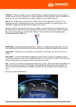
SYNERGY
- synergic settings. The user selects the basic welding parameters such as the type of
material, thickness of the material to be welded, diameter of the welding wire. Other parameters of
the device are selected automatically using the database of uploaded programs.
MIG mode
- welding using individual user settings. The system suggests the selection of key
welding parameters, indicating the thickness of the welded material when adjusting them. This
information suggests to the user that the settings are correct.
LIFT-TIG
- TIG lift mode (ignition of the arc by rubbing) - welding with a tungsten electrode in an
inert gas shield. In order to carry out welding by this method, it is necessary to retrofit the device
TIG torch with shielding gas control in the handle as in the photo below.
This handle is not a
standard equipment of the set.
MMA MODE -
welding with coated electrode. In addition to welding current adjustment, the user
can additionally set ARC-FORCE, HOT START and enable or disable the VRD protection system.
ARC FORCE
- Stabilizes the arc regardless of fluctuations in its length, reduces the amount of
spatter.
HOT-START
- a function that makes welding easier. When the arc strikes, the welding current is
temporarily increased to heat up the material and electrode at the point of contact, and to properly
shape the penetration and weld face at the initial stage of welding.
VRD
- the device has a VRD (Voltage Reduction Device) system, which for welding mode MMA with
electrodes reduces the open circuit voltage, which significantly increases the user's safety. In
special cases of using electrodes with high arc ignition current, problems with its initiation may
occur.
D
. Synergy function (MIG/MAG )
B.
LANGUAGE SELECTION
The device allows you to set the following control languages: English, German, Dutch, French,
Spanish.
Turn the red knob of the font panel to select the language then press for confirmation.
C.
CHOICE OF WELDING METHOD
This page allows you to select welding methods as below:
Synergy, MIG, LIFT-TIG, MMA
Turn the red knob of the font panel to select the welding mode then press for confirmation.
6. PANEL OPERATION
A.
DESCRIPTION OF THE CONTROL PANEL
1. LCD display
2. Function selection button, to select the previous menu, holding for 5 seconds to save the current
setting in memory.
3. Button to return to the previous menu. (additionally held for 5 seconds to return to the factory
settings (RESET)).
4. Adjustment knob,
Turn - Select and Adjust.
Press - Confirm and Switch to next.
5. Button for Confirmation or Enter.
6. Function selection button, to select the next menu, holding for 5 seconds to recall memories;
The device has 18 memory programs.
DOUBLE PULSE MODE
Welding with the MIG / MAG method with double pulse we get a high level of face appearance (husk
effect). In addition, the use of automatic wire feed affects welding performance. The MIG / MAG
method with double pulse allows the regulation of current pulsation (pulse balance) and adjustment
of the wire feed speed. Thanks to this, we improve the appearance of the weld. When MIG / MAG
welding with double pulse, current pulses occur in two ranges. The sequential system of our devices
automatically combines two levels of pulses.
The benefits of using the MIG MAG method with double pulse are:
1.
MIG / MAG double pulse welding is faster than TIG welding.
2.
MIG / MAG double pulse welding achieves high aesthetics like the TIG method.
3.
MIG / MAG double pulse welding results in less deformation than TIG.
- Unscrew the regulator valve before starting to weld.
Always close the cylinder valve after
welding.
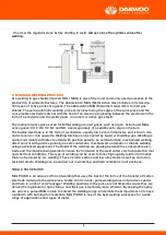
5. MIG/MAG WELDING PROCESS
Arc welding in gas shields (marked MIG / MAG) is one of the most commonly used processes in the
production of welded structures. The abbreviation MAG (Metal Active Gas) includes in its descrip-
tion types of active protective gases. The abbreviation MIG (Metal Inert Gas) refers to inert gas
shields. The semi-automatic welding process involves fusing the edges of the work piece and the
consumable electrode material with the heat of an electric arc glowing between the electrode in the
form of a solid wire and the welded part, in an inert or active gas shield
.
The main protective gases used for MIG welding are inert gases such as argon, helium and MAG
active gases: CO2, H2, O2, N2 and NO, used separately or as additives to argon or helium.
The fusible electrode is in the form of a solid wire, usually 0.6 1.2 mm in diameter, and is fed in mm,
and is fed in m / min upwards. Welding torches can be cooled by liquid or shielding gas. Welding is
carried out mainly with direct current with positive polarity, as semiautomatic, mechanized welding,
direct current with positive polarity, as semi-automatic, mechanized, automatic or robotic welding
using specialized equipment. The shield of the welding arc glowing between the consumable elec-
trode and the material being welded ensures the formation of the weld under very favorable thermal
and chemical conditions. This type of welding can be used to make high-quality joints of all metals
that can be joined by arc welding. These include: carbon and low alloy steels as well as corrosion
resistant steels. Welding can be carried out in workshop and field conditions in all positions.
SINGLE PULSE MODE
MIG PULSE is an advanced form of welding that uses the best of the forms of the transfer of molten
electrode material to the work piece. Unlike short circuits, pulse welding does not produce spatter
and there is a risk of cold "leakage". Welding positions in the pulse are not limited because they are
derived from globular or spray forms, and their use is definitely more efficient. By cooling the spray
arc process, pulsed MIG is able to extend the welding range, and smaller heat input does not cause
a problem with burning thin materials. MIG PULSE is one of the best welding processes for a wide
range of applications and types of metal.
Welding wire spool assembly:
The device is equipped with professional wire feeder, it has 4 rolls feeder enabling work with 2
handles max 4mb when welding with steel wire and with 3mb when welding with aluminum alloy
wire, The welding wire holder allows the installation of reels with a diameter of 300mm-15kg.
- Lift the side cover of the semi-automatic housing.
-
Ensure that the rollers fitted in the drive unit match the type and diameter of wire used. Rolls
should be used for steel wires with "V" shaped grooves, while for aluminum wires with "U" type
grooves.
- Apply welding wire spools to the spool clamping mechanism, paying attention that the unwinding
direction of the wire is consistent with the direction of the wire's entry into the drive unit. Lock the
spools before slipping by tightening the nut on the spool mounting body.
-
The end of the wire should be straightened or cut off a bent section.
- To feed wire into the feeder, release the pressure of the feed rollers.
- Insert the end of the wire into the guide located at the back of the feeder and route it over the drive
roller by inserting it into the welding gun stub.
-
Tighten the wire in the drive roller groove and tighten.
-
Remove the gas nozzle from the burner and unscrew the contact tip.
-
Turn the device on.
-
Unwind the welding gun cable so that it is straight. ATTENTION! Do not drive the welding torch
ends towards the face or other people.
-
Press the welding button on the welding gun and hold it until the wire appears behind the torch.
-
When the end of the welding wire passes through the connector in the torch, release the button
approx. 5 cm and replace the contact tip and gas nozzle.
-
Adjust the clamping force by turning the knob, clockwise-increases the clamping force, to the left-
decreases the clamping force. Too low clamping force will cause the drive roller to slip. Too much
pressure increases the feed resistance and deforms the wire.
We recommend placing the wire into the welding gun with the valve on the shielding gas
cylinder closed. This will reduce its unnecessary losses.
Installation of shielding gas cylinders:
- A cylinder with a suitable shielding gas must always be properly secured against falling over. If
possible, attach to an approved welding carriage with the MIG / MAG device. The trolley is not
standard equipment of the set.
- Connect the semi-automatic machine to the cylinder with a suitable hose.
- Before starting work, specify the place where the device is to be operated.
-
The device should be connected to the network so that it can be freely manipulated at all times.
-
The power cord should not be taut during operation.
-
Do not use the device on a surface that may cause it to tip over.
- To move the device, use only the handle on the front of the device. Do not pull on the welding or
power cord.
-
Moving and transporting the device and cylinders with technical gases should be carried out
separately. Only carry the machine using the factory carrying handles.
-
Incorrect use is prohibited.
ATTENTION!
The heating test was carried out at ambient temperature and the duty cycle (load factor) at 25
°C
was
determined as a result of the simulation.
The device is intended for conducting professional welding works in industrial conditions by person-
nel having valid qualification certificates in accordance with applicable standards.
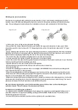
Earth handle connected to the negative socket -
Welding with negative polarity -
(
welding with flux cored wire - FCAW)
Welder's current plug connected to the negative socket -
(
EURO
)
Earth clamp connected to the positive
WARNING!
To start working with self-shielding wire, change the polarity inside the device - on the wire feeder.
BEFORE YOU WORK:
- Check the voltage, number of phases and frequency of the power supply before connecting the
device to the mains.
- Power supply voltage parameters are given in the chapter with technical data and on the rating
plate of the device.
- Check the connection of the grounding wires of the device to the mains.
- Ensure that the power supply network can provide coverage of the input power demand for this
device under normal operating conditions. The fuse size, the parameters of the power cord are
given in the technical data and on the rating plate. Connection and replacement of the power cord
and plug should be made by a qualified electrician.
- Remove all flammable materials from the welding area.
-
Use appropriate protective clothing for welding: gloves, apron, work boots, mask or visor with
appropriate certificates.
DEVICE CONNECTION FOR THE MIG / MAG METHOD
- To extend the service life and ensure reliable operation of the device, observe the following rules:
- The device should be placed in a well-ventilated room with free air circulation.
- Do not place the device on wet ground.
- Use an electrode wire with diameter and spool weight in accordance with the manufacturer's
instructions (D200, max. 15 kg). Check the technical condition of the device and welding cables on
an ongoing basis.
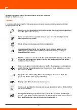
Please read carefully this user manual before using this machine.
Keep it for the future use.
1. SAFETY
It is imperative that you read the following signs and safety rules to protect your own and other
people's health and life.
Содержание DAMIG-350GDL
Страница 26: ...26 11 EXPLODED VIEW...
Страница 27: ...EN 27...
Страница 30: ...www daewoopowerproducts com Manufactured under license of Daewoo International Corporation Korea...


