background image

8

Installation Instructions

Gas Line Connection

 WARNING

Verify that the gas supply meets specifications before 

• 

connection. See page 3.
The maximum gas supply pressure to the regulator 

• 

must never exceed ½ pounds per square inch (psi) or 

3.5 kPa.
Do not install or use the cooktop without the included 

• 

gas regulator installed.
Ensure that the arrow on the regulator points in the 

• 

direction of the gas flow, towards the cooktop.
Do not apply excessive pressure when tightening gas 

• 

connections and fittings.
Do not use Teflon tape or plumber’s putty on flexible 

• 

gas line connections.
Test the gas lines for leaks as instructed before use. 

• 

Do not use a flame to check for leaks. 
The gas supply pressure for testing the regulator set-

• 

ting shall be at least 1 inch water column (249Pa) 

above the specified manifold pressure. See page 3.
The cooktop and shut-off valve must be disconnected 

• 

from the gas supply piping system during any pres-

sure testing exceeding ½ p.s.i. (3.5 kPa).
The cooktop must be isolated from the gas supply 

• 

piping system by closing the shut-off valve to the 

cooktop during any gas supply piping system pres-

sure testing equal to or less than ½ p.s.i. (3.5 kPa).
For LP gas installations, the LP gas tank must have 

• 

its own high-pressure regulator in addition to the 

pressure regulator supplied with the cooktop.

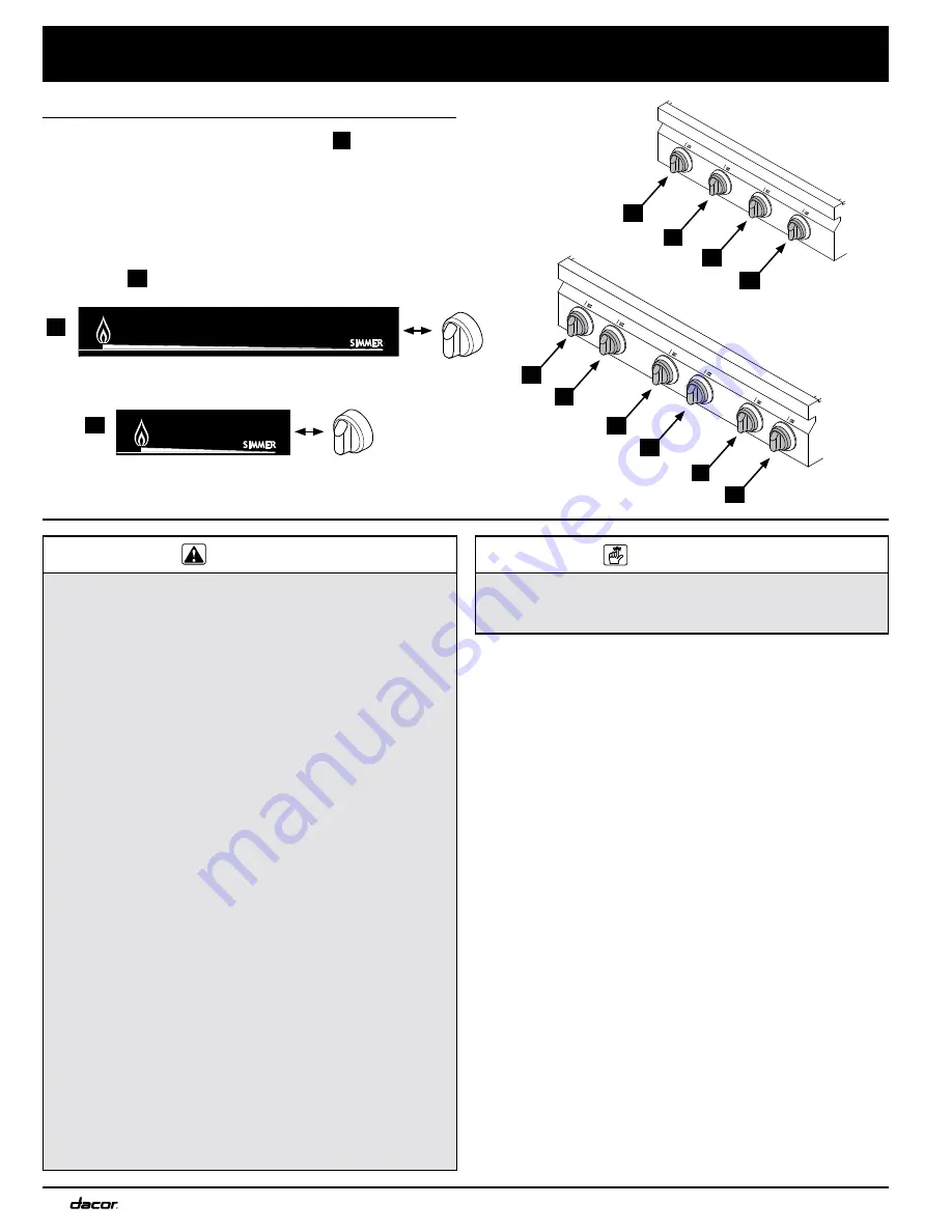
Knob Installation

Attach the SimmerSear burner knobs 

1. 

 A 

 as shown 

below. The SimmerSear knobs have a wider space 

between the large flame icon and the simmer icon than 

the standard burner knobs. Align the “D-shaped” open-

ing on the back of each knob with the end of the valve 

shaft. Carefully push each knob on until it stops.
Attach the remaining knobs which operate the standard 

2. 

burners 

 B 

.

SimmerSear Burner Knob Layout

Standard Burner Knob Layout

 IMPORTANT

Within the Commonwealth of Massachusetts, this 

appliance must be installed by a licensed plumber or gas 

fitter.

Attach the gas pressure regulator (included with the 

1. 

cooktop) to the 3/4” (19 mm) male NPT gas inlet on 

the cooktop. The inlet is located on the bottom, at the 

right rear portion of the chassis. For tight installations, 

the regulator may be installed upstream from the pipe 

nipple, anywhere between the shut-off valve and the 

cooktop. For best performance, minimize gas pressure 

loss by attaching the regulator as close as possible to 

the cooktop gas inlet.
Complete connection of the gas supply to the cooktop 

2. 

by installing a minimum ½” flexible gas line (not includ-

ed) between the pressure regulator and the shut-off 

valve.
Check for gas leaks:

3. 

Turn all cooktop control valves to the 

◊ 

OFF

 position.

Turn on the gas supply valve and check all lines 

◊ 

and connections for leaks using a soap and water 

solution or a gas leak detector.
Turn the gas supply valve off.

◊ 


 A 


 B 


Control Panel - 

DRT304S

Control Panel - 

DRT366S


 B 


 B 


 A 


 B 


 A 


 A 


 B 


 B 


 B 


 B 


Содержание DRT304S

Страница 1: ...ion Instructions Distinctive Series Cooktop Models DRT304S DRT366S Part No 106522 Rev C THIS APPLIANCE HAS BEEN TESTED IN ACCORDANCE WITH THE LATEST EDITION OF ANSI Z21 1 STANDARD FOR HOUSEHOLD GAS AP...

Страница 2: ...ilding inspector s use 2009 Dacor all rights reserved If You Need Help If you have questions or problems with installation contact your Dacor dealer or the Dacor Customer Service Team For repairs to D...

Страница 3: ...ANT If you smell gas Do not use or light any appliance Do not touch any electrical switch or use any electri cal devices including the telephone in your building From a neighbor s phone immediately ca...

Страница 4: ...m panying it This cooktop is not intended for commer cial or laboratory use DO NOT TOUCH THE SURFACES OF THE COOKTOP OR THE SURROUNDING AREAS DURING OR IMMEDIATELY AFTER USE WARNING General Safety Pre...

Страница 5: ...liance should be installed in accordance with the National Fuel Gas Code ANSI Z223 1 NFPA 54 The gas service must be installed by a qualified profes sional Be certain that the cooktop being installed...

Страница 6: ...olid and level The countertop overhang on the sides of the cutout shown on the following pages covers the recessed por tions of the cooktop behind the control panel and cre ates a seamless look for th...

Страница 7: ...ntinued on following pages See note 2 2 See Cabinet Countertop Dimensions Top View 3 Not applicable for cabinets more than a horizontal distance of 10 254mm from the edge of the cooktop 1 Vertical to...

Страница 8: ...form for hold down bolts Gas electrical utility cut out in right rear corner of mounting platform 8 W X 6 D 203 mm X 152 mm if gas and electrical are routed through bottom 1 2 13 mm countertop overhan...

Страница 9: ...S Part Quantity for Model DRT304S Quantity for Model DRT366S Knobs standards 3 4 Knobs SimmerSear 1 2 10 inch grate none 1 12 inch grate none 2 14 inch grate 2 none Standard burner cap small 1 2 Stand...

Страница 10: ...cooktop Knob Installation Attach the SimmerSear burner knobs 1 A as shown below The SimmerSear knobs have a wider space between the large flame icon and the simmer icon than the standard burner knobs...

Страница 11: ...ndentations on the bottom of the burner ring with the pins on the top of the burner base Set the outer SimmerSear burner cap s on top of the 2 burner ring s Make sure the burner ring is centered on to...

Страница 12: ...e power plug is connected to the electrical outlet and that power is turned on at the circuit breaker or fuse box Check to make sure that all burner parts are properly seated If the burner continues t...

Страница 13: ...TOR RL FL FR RR B W B FL INDICATOR LIGHT W B W B W B B W W W W Single Point Spark Module Single Point Spark Module Single Point Spark Module Single Point Spark Module 120V 60Hz 0 25A POWER SUPPLY WIRI...

Страница 14: ...T FR INDICATOR LIGHT B B W W W B B B RC INDICATOR LIGHT B W RR INDICATOR LIGHT B W RR RC FC FR RL FL B B Single Point Spark Module W W Single Point Spark Module Single Point Spark Module Single Point...

Страница 15: ......

Страница 16: ...Dacor 600 Anton Blvd Suite 1000 Costa Mesa CA 92626 Phone 800 793 0093 Fax 626 403 3130 www Dacor com...

Отзывы: