background image

STAT

Solid green

The diagnostic test was successfully completed.

Solid amber

The self-diagnostics system has detected a fault.

Light off

The system is down, the switch is booting up, or the network OS
did not boot up normally.

Link/Activity/Speed
(per optical port)

Solid green

There is a secure 10/40 Gbps connection at the port.

Blinking green

There is reception or transmission occuring at the port.

Solid amber

There is a secure 1000 Mbps connection at the port.

Blinking amber

There is reception or transmission occuring at the port.

Light off

No link.

Link/Activity   (per   RJ-
45 port)

Solid green

There is a secure 1000 Mbps connection at the port.

Blinking green

There is reception or transmission occuring at the port.

Solid amber

There is a secure 10/100 Mbps connection at the port

Blinking amber

There is reception or transmission occuring at the port.

Light off

No link.

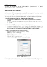
Installation Guidelines

This section will discuss the hardware installation guidelines that the user must follow in
order to properly and safely install this switch into the appropriate environment.

Visually inspect the power cord and see that it is fully secured to both the power
connector, on the switch, and the electrical outlet that supplies power.

Install   the   switch   in  a   fairly   cool   and   dry   place   within   the   acceptable   operating
temperature and humidity ranges.

Install the switch in a site free from strong electromagnetic field generators such as
motors, vibration, dust, and direct exposure to sunlight.

Installing the Switch without a Rack

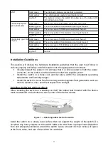
When installing the switch on a desktop or shelf, the rubber feet included with the device
must be attached on the bottom at each corner of the device’s base.

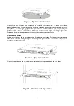
Figure 1 — Attaching rubber feet to the switch

Install the switch on a sturdy, level surface that can support the weight of the switch. Do
not place any heavy objects on the switch. Make sure that there is proper heat dissipation
from and adequate ventilation around the switch. Leave at least 10 cm (4 inches) of space
at the front, sides, and rear of the switch for ventilation.

3

Содержание DXS-5000-54S

Страница 1: ...nk DXS 5000 54S 48 port 10G SFP 6 port 40G QSFP interfaces data center switch with 2 front to back AC PSUs 4 front to back fan modules L3 48 10GBase X SFP 6 40GBase X QSFP 2 AC 4 Quick Installation Gu...

Страница 2: ...t USB 2 0 Type A port for connecting a USB storage device Mini USB console port Mini USB console port for connecting to a PC with a mini USB console cable included in the package The Command Line Inte...

Страница 3: ...hardware installation guidelines that the user must follow in order to properly and safely install this switch into the appropriate environment Visually inspect the power cord and see that it is fully...

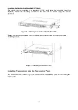
Страница 4: ...he switch using the screws provided Figure 2 Attaching rack mount brackets to the switch Fasten the mounting brackets in any available open space in the rack using the rack mounting screws Figure 3 In...

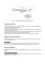
Страница 5: ...re the switch is installed 4 Verify that the ground connections on the switch and the rack are securely attached Plugging in the AC Power Cord Plug one end of the AC power cord into the power socket o...

Страница 6: ...on one end and a mini USB connection on the other To connect the mini USB console port on the switch to the computer Connect the male DB9 connector on the console cable shipped with the switch to the...

Страница 7: ...age to reboot the switch is to unplug and re insert the power cable from and into the power receptacle on the back of the switch Then select an operating system to boot the switch in either D Link OS...

Страница 8: ...0 45 5 c 2 6 7 2012 D 2013 E 2014 F 2015 G 2016 H 2017 I 2018 J 2019 0 2020 1 2021 2 2022 1 2 9 A B D Link 8...

Страница 9: ...54S 2 RJ 45 mini USB 4 2 19 DXS 5000 54S 10GBase X SFP 48 SFP 10 40GBase X QSFP 6 QSFP 40 USB 2 0 USB 2 0 Type A USB mini USB mini USB mini USB CLI 10 100 1000Base T RJ 45 Out of band 10 100 1000 PSU...

Страница 10: ...FAN STAT Link Activity Speed 10 40 1000 Link Activity RJ 45 1000 10 100 10...

Страница 11: ...1 10 19 2 3 11...

Страница 12: ...DXS 5000 54S SFP QSFP 4 1 2 3 4 DXS 5000 54S CLI SNMP 12...

Страница 13: ...CLI CLI SNMP SNMP DXS 5000 54S SNMP 1 2c 3 mini USB mini USB mini USB mini USB RS 232 RS 232 mini USB 1 RS 232 2 mini USB COM1 COM2 115200 8 1 VT100 Terminal keys 13...

Страница 14: ...5 COM ONIE D Link 14...

Страница 15: ...band PSU 1 PSU 2 FAN STAT Link Activity Speed Link Activity RJ 45 Reset IEEE 802 3z 1000Base X IEEE 802 3ae 10GBase X IEEE 802 3ba 40GBase X IEEE 802 3 10Base T IEEE 802 3u 100Base TX IEEE 802 3ab 10...

Страница 16: ...294 83 1 006 58 MTBF 205 000 74 62 4 0 45 C 40 70 C 5 95 5 95 cULus CCC BSMI CB CE EMI EMC FCC IC CCC CB CE BSMI 16...

Страница 17: ...C Negruzzi 8 Tel 373 22 80 81 07 E mail info dlink md 169 375 17 218 13 65 E mail support dlink by c 143 7 727 378 55 90 E mail almaty dlink ru 3 23 5 374 10 39 86 67 info dlink am Lietuva Vilnius irm...

Отзывы: