background image

4  Configuration


D-Link DXS-1210 Series User Manual


3

3

5

5


Enter a page number and click the 

Go 

button to navigate to a specific page when multiple pages exist. 


L2 Features > FDB > Static FDB > Multicast Static FDB 

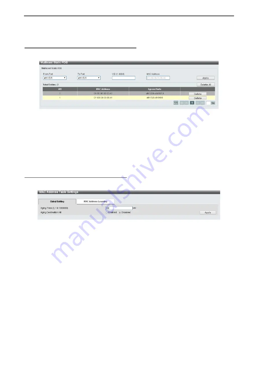
The Multicast Static FDB page allows you to view and configure the static multicast forwarding settings on 
the Switch. 


Figure 4.58 – L2 Features > FDB > Static FDB > Multicast Static FDB 


From Port / To Port: 

Enter


the appropriate port range used for the configuration. 

VID (1-4094): 

Enter


the VLAN ID of the VLAN the corresponding MAC address belongs to.  

MAC Address: 

Enter


the static destination MAC address of the multicast packets. This must be a multicast 

MAC address. The format of the destination MAC address is 01-XX-XX-XX-XX-XX.  


Click the 

Apply

 button to save your settings.  And click the 

Delete All 

button to remove all the entries. Click 

the 

Delete

 button to remove the specific entry. 

Enter a page number and click the 

Go 

button to navigate to a specific page when multiple pages exist. 


L2 Features > FDB > MAC Address Table Settings 

The 

MAC Address Table Settings 

page allows you to view and configure the MAC address table’s global 

settings. 


Figure 4.59 – L2 Features > FDB > MAC Address Table Settings – Global Setting 

 
Aging Time:

 Enter the MAC address table’s aging time value. This value must be between 10 and 1000000 

seconds. Entering 0 will disable MAC address aging. By default, this value is 300 seconds. 

Aging Destination Hit: 

Select to enable or disable the aging destination hit function.


Click the 

Apply 

button to save your settings. 


After clicking the MAC Address Learning tab, the following page will appear. 

Содержание DXS-1210 Series

Страница 1: ...D X S 1 2 1 0 S e r i e s L 21 0G i g a b i t E t h e r n e t S w i t c hS e r i e s V e r 1 1 0 ...

Страница 2: ......

Страница 3: ...ing Web based Management 8 Supported Web Browsers 8 Connecting to the Switch 8 Login Web based Management 8 Smart Wizard 9 Web based Management 9 4 Configuration 10 Smart Wizard Configuration 10 IPv4 Information 10 SNMP Settings 10 User Accounts Settings 11 Web based Management 11 Tool Bar Save Menu 12 Save Configuration 12 Tool Bar Tool Menu 13 Firmware Information 13 Configuration Information 13...

Страница 4: ... Management User Accounts Settings 25 Management Password Encryption 25 Management SNMP SNMP Global Settings 26 Management SNMP SNMP View Table Settings 27 Management SNMP SNMP Community Table Settings 27 Management SNMP SNMP Group Table Settings 28 Management SNMP SNMP Engine ID Local Settings 28 Management SNMP SNMP User Table Settings 29 Management SNMP SNMP Host Table Settings 30 Management RM...

Страница 5: ...P Management Address List 54 L2 Features LLDP LLDP Basic TLVs Settings 54 L2 Features LLDP LLDP Dot1 TLVs Settings 55 L2 Features LLDP LLDP Dot3 TLVs Settings 55 L2 Features LLDP LLDP MED Port Settings 56 L2 Features LLDP LLDP Statistics Information 56 L2 Features LLDP LLDP Local Port Information 57 L2 Features LLDP LLDP Neighbor Port Information 58 L3 Features ARP ARP Aging Time 59 L3 Features AR...

Страница 6: ...5 Command Line Interface 101 To connect a switch via TELNET 101 Logging on to the Command Line Interface 101 CLI Commands 101 102 config ipif 102 logout 103 ping 103 reboot 104 reset config 104 show ipif 105 show ipv6 105 show switch 106 config account username 106 save 107 boot image 107 debug info 108 debug show tech support 108 Appendix A Technical Specifications 110 Hardware Specifications 110...

Страница 7: ...st letter capitalized refers to the DSX 1210 Series switch and switch first letter lower case refers to other Ethernet switches Some technologies use switch bridge and switching hubs interchangeably and all are commonly accepted terms for Ethernet switches A NOTE indicates important information that helps you make better use of the device A CAUTION indicates potential property for property damage ...

Страница 8: ...e 802 3ad LACP SNTP LLDP and Loopback Detection to enhance performance and network resiliency Extensive Layer 3 Features These switches include functions such as IP interface static route IPv6 Static Route and ARP to enhance performance and network resiliency QoS The switches support bandwidth control and 802 1p priority queues enabling users to run bandwidth sensitive applications such as streami...

Страница 9: ...CAUTION The MiniGBIC ports should use UL listed Optical Transceiver product Rated Laser Class I 3 3Vdc Rear Panel Figure 1 2 DXS 1210 10TS Rear Panel Power Connect the AC power cord to this port DXS 1210 12TC 8 port 10GBASE T and 2 port 10G SFP also with additional 2 port 10GBASE T SFP combo port L2 10 Gigabit Ethernet Switch Front Panel Figure 1 3 DXS 1210 12TC Front Panel Power LED The Power LED...

Страница 10: ...LED lights up when the fan has runtime failure and is brought offline Port Link Act Speed LED 1 10 11F 12F The Link Act Speed LED flashes which indicates a network link through the corresponding port Blinking indicates that the Switch is either sending or receiving data to the port When a port has an amber light this indicates that the port is running on 100M or 1000M When it has a green light it ...

Страница 11: ...If you are not sure of the type of power source required consult your service provider or local reseller Also be sure that attached devices are electrically rated to operate with the power available in your location Use only approved power cable s If you have not been provided with a power cable for your system or for any AC powered option intended for your system purchase a power cable that is ap...

Страница 12: ...em is found missing or damaged please contact the local reseller for replacement Step 2 Switch Installation For safe switch installation and operation it is recommended that you Visually inspect the power cord to see that it is secured fully to the AC power connector Make sure that there is proper heat dissipation and adequate ventilation around the switch Do not place heavy objects on the switch ...

Страница 13: ...e Switch can now be connected to the AC power Connect the AC power cord to the rear of the switch and to an electrical outlet preferably one that is grounded and surge protected Figure 2 4 Plugging the switch into an outlet Power Failure As a precaution the switch should be unplugged in case of power failure When power is resumed plug the switch back in ...

Страница 14: ... Switch monitor the network status and display statistics using a web browser Supported Web Browsers The embedded Web based Management currently supports the following web browsers Internet Explorer 8 or later version Chrome Firefox Safari Connecting to the Switch You will need the following equipment to begin the web configuration of your device 1 A PC with a RJ 45 Ethernet connection 2 A standar...

Страница 15: ...uages including English Traditional Chinese Simplified Chinese German Spanish French Italian Portuguese Japanese and Russian By default the Username and Password are empty and the language is English Figure 3 3 Login Dialog Box Smart Wizard After a successful login the Smart Wizard will guide you through essential settings of the D Link DXS 1210 Series Switch Please refer to the Smart Wizard Confi...

Страница 16: ...onfigurations on 3 steps for the IP Information access password and SNMP Select Static to manually enter a new IP Address Netmask and Gateway address or select DHCP to automatically receive IP settings from a DHCP server Click the NEXT button to enter the SNMP settings page The IP address is allowed for IPv4 and IPv6 address If you are not changing the settings click Exit button to go back to the ...

Страница 17: ...r Accounts Settings page allows you to quickly specify the user account function Enter the User Name Privilege Password Type and Password Click Apply Save to save the configuration Figure 4 3 User Accounts Setting in Smart Wizard Web based Management After clicking the Exit button in the Smart Wizard you will see the screen below ...

Страница 18: ...t status of your Switch by clicking the model name on top of the function tree At the upper right corner of the screen the username and current IP address will be displayed Under the username is the Logout button Click this to end this session NOTE If you close the web browser without clicking the Logout button first then it will be seen as an abnormal exit and the login session will still be occu...

Страница 19: ...rmware Backup and Upgrade Figure 4 7 Tool Menu Firmware Information Display the firmware for the 2 firmware images including the image that has been booted and the image that is selected for the next reboot Figure 4 8 Tool Menu Firmware Information Configuration Information Display information for the Switch configuration This includes the configuration that has been loaded and the configuration t...

Страница 20: ...k Backup Figure 4 12 Tool Menu Firmware Upgrade Backup Firmware Backup to HTTP Firmware Backup to HTTP Backup Firmware Backup to TFTP To save a backup of the firmware using TFTP enter the TFTP server IP address the source URL and the destination URL Click Backup Figure 4 13 Tool Menu Firmware Upgrade Backup Firmware Backup to TFTP Configuration Upgrade Backup Configuration Restore from HTTP To res...

Страница 21: ...TP Server IP Select IPv4 or IPv6 and enter the IP address Source Select the source configuration file Startup config when checking the box only the current startup configuration file will be backed up which may be stored in the Config 1 or Config 2 location Destination URL Enter the destination URL for the backup Log Backup Log Backup to HTTP To save the log to a file and click Backup Figure 4 18 ...

Страница 22: ...art the Switch Figure 4 22 Tool Menu Reboot System Destination Select the configuration destination to be saved Startup config When checking the box only the current startup configuration file will be backed up which may be stored in the Config 1 or Config 2 location Tool Bar Smart Wizard By clicking the Smart Wizard button you can re run to the Smart Wizard if you wish to make any changes Tool Ba...

Страница 23: ...4 Configuration D Link DXS 1210 Series User Manual 1 17 7 Figure 4 24 User Guide Micro Site ...

Страница 24: ...ide more detailed description of each feature and function Figure 4 25 Function Tree Device Information The Device Information provides an overview of the switch including essential information such as firmware hardware information and IP settings Figure 4 26 Device Information System System Information The System Setting page allows you to configure basic system information System Information Set...

Страница 25: ...ion between the Switch port and another device capable of a Gigabit connection The master setting 1000M Master will allow the port to advertise capabilities related to duplex speed and physical layer type The master setting will also determine the master and slave relationship between the two connected physical layers This relationship is necessary for establishing the timing control between the t...

Страница 26: ...able the notifications when exiting from the error disabled state Notification Rate 0 1000 Enter the number of traps per minute The packets that exceed the rate will be dropped The value is between 0 and 1000 Click the Apply button to save your settings Error Disable Recovery Settings ErrDisable Cause Specify the error disable causes Options to choose from are All Port Security Storm Control ARP R...

Страница 27: ...ce that will be used The default option is VLAN VID 1 4094 Specifies the VLAN ID The possible range is 1 4094 Click the Apply button to save your settings Buffer Log Settings Buffer Log State Select to enable or disable the buffer log state The options are Enable Disable and Default Severity Select the severity value of the type of information that will be logged The values are 0 Emergencies 1 Ale...

Страница 28: ...y Select the facility value The values must be between 0 and 23 Click the Apply button to save your settings System System Log System Log The System Log page displays the system logs on the Switch Figure 4 34 System System Log System Log System Time and SNTP Clock Settings The Clock Settings page allows you to configure the time settings for the Switch Figure 4 35 System Time and SNTP Clock Settin...

Страница 29: ... that daylight saving time will end To Time In HH MM Select the time of the day that daylight saving time will end Offset Enter the number of minutes to add during daylight saving time The default value is 60 The range of this offset is 30 60 90 and 120 The Date Setting can be configured below From Date of the Month Select date of the month that daylight saving time will start From Month Select th...

Страница 30: ...utton to add the SNTP server System Time Range The Time Range page allows you to view and configure the time range settings for the Switch Figure 4 38 System Time Range Range Name Enter a name for the time range The name can be up to 32 characters long From Week To Week Select the starting and ending days of the week that will be used for this time range Tick the Daily option to use this time rang...

Страница 31: ... system information and change any of the system configuration settings expressed in this guide Figure 4 39 Management User Accounts Settings User Name Enter the name of the user name The name can be up to 32 characters long Privilege 1 15 Select the privilege level for this account The value is between 1 and 15 Password Type Select a password type for this user account The options are None Plain ...

Страница 32: ...obal Settings SNMP Global State Select to enable or disable the SNMP feature SNMP Response Broadcast Request Select to enable or disable the server to response to broadcast SNMP GetRequest packets SNMP UDP Port 0 65535 Enter the SNMP UDP port number The value is between 0 and 65535 Trap Source Interface Specify the interface whose IP address will be used as the source address for sending the SNMP ...

Страница 33: ... the Switch s SNMP agent Figure 4 44 Management SNMP SNMP Community Table Settings Key Type Select the key type for the SNMP community Select either Plain Text or Encrypted Community Name Select an alphanumeric string of up to 32 characters that is used to identify members of an SNMP community This string is used like a password to give remote SNMP managers access to MIB objects in the Switch s SN...

Страница 34: ...is function is only available when you select SNMPv3 security level NoAuthNoPriv No authorization and no encryption for packets sent between the Switch and SNMP manager AuthNoPriv Authorization is required but no encryption for packets sent between the Switch and SNMP manager AuthPriv Both authorization and encryption are required for packets sent between the Switch and SNMP manger IP Address List...

Страница 35: ...field will require the user to enter a password SHA Select that the HMAC SHA authentication protocol will be used This field will require the user to enter a password Priv Protocol by Password Select either None or DES56 and then enter a password for SNMPv3 encryption in the right column None Select to not use any authorization DES56 Select to use DES 56 bit encryption based on the CBC DES DES 56 ...

Страница 36: ...ization but with no encryption of packets sent between the Switch and a remote SNMP manager AuthPriv Select to require authorization and packets sent between the Switch and a remote SNMP manger will be encrypted UDP Port 0 65535 Enter the UDP port number The default trap UDP port number is 162 The range of UDP port numbers is from 0 to 65535 Note Some port numbers may conflict with other protocols...

Страница 37: ...samples may include interface definitions or polling periods Figure 4 51 Management RMON RMON History Settings The History Control Configuration contains the following fields Port Select the port from which the RMON information was taken Index 1 65535 Indicates the history control entry number Buckets Requested 1 50 Enter the number of buckets that the device saves Interval 1 3600 secs Indicates i...

Страница 38: ...alue against the thresholds The possible field values are Delta value Subtracts the last sampled value from the current value The difference in the values is compared to the threshold Absolute value Compares the values directly with the thresholds at the end of the sampling interval Falling Threshold 0 2 31 1 Displays the falling counter value that triggers the falling threshold alarm Falling Even...

Страница 39: ...for Telnet management of the Switch The well known TCP port for the Telnet protocol is 23 Click Apply to save your settings Web Settings Web State Select to enable or disable Web based configuration Port 1 65535 Enter the TCP port number used for Telnet management of the Switch The well known TCP port for the Telnet protocol is 80 Click the Apply button to save your settings Management Session Tim...

Страница 40: ...DDP port state Click the Apply button to save your settings L2 Features FDB Static FDB Unicast Static FDB The Unicast Static FDB page allows you to view and configure the static unicast forwarding settings on the Switch Figure 4 57 L2 Features FDB Static FDB Unicast Static FDB Port Drop Allows the selection of the port number on which the MAC address entered resides This option could also drop the...

Страница 41: ...dress is 01 XX XX XX XX XX Click the Apply button to save your settings And click the Delete All button to remove all the entries Click the Delete button to remove the specific entry Enter a page number and click the Go button to navigate to a specific page when multiple pages exist L2 Features FDB MAC Address Table Settings The MAC Address Table Settings page allows you to view and configure the ...

Страница 42: ...e used for this configuration MAC Address Enter the MAC address that will be used for this configuration Click the Find button to locate a specific entry based on the information entered Click the Clear Dynamic by Port button to clear the dynamic MAC address listed on the corresponding port Click the Clear Dynamic by VLAN button to clear the dynamic MAC address listed on the corresponding VLAN Cli...

Страница 43: ...utton to navigate to a specific page when multiple pages exist L2 Features Asymmetric VLAN The Asymmetric VLAN page allows you to configure the asymmetric VLAN function on this switch Figure 4 63 L2 Features Asymmetric VLAN Asymmetric VLAN State Select to enable or disable the Asymmetric VLAN function Click the Apply button to save your settings L2 Features VLAN Interface The VLAN Interface page a...

Страница 44: ...rotocol RSTP as defined by the IEEE 802 1w specification a version compatible with the IEEE 802 1D STP and the Multiple Spanning Tree Protocol MSTP as defined by the IEEE802 1 specification RSTP can operate with legacy equipment implementing IEEE 802 1D however the advantages of using RSTP will be lost The IEEE 802 1w Rapid Spanning Tree Protocol RSTP evolved from the 802 1D STP standard RSTP was ...

Страница 45: ...is value is between 0 and 61440 By default this value is 32768 The lower the value the higher the priority Click the Apply button to save your settings STP Configuration Bridge Max Age 6 40 Enter the bridge s maximum age value here This value must be between 6 and 40 seconds By default this value is 20 seconds The maximum age value may be set to ensure that old information does not endlessly circu...

Страница 46: ...he switch level spanning tree but the root bridge concept is replaced with a root port concept A root port is a port of the group that is elected based on port priority and port cost to be the connection to the network for the group Redundant links will be blocked just as redundant links are blocked on the switch level The STP on the switch level blocks redundant links between switches and similar...

Страница 47: ...when a bridge interconnects two regions each region needing a separate spanning tree BPDU filtering functions only when STP is disabled either globally or on a single interface The possible field values are Disabled BPDU filtering is enabled on the port Enabled BPDU forwarding is enabled on the port if STP is disabled Priority Select the priority of each port Selectable range is from 0 to 240 and ...

Страница 48: ...Port Information The MSTP Port Information page allows you to configure the MSTP Interface settings Figure 4 71 L2 Features STP MSTP Port Information Port Enter the port to find Click the Clear Detected Protocol button to clear the detected protocol settings for the port selected Click Find to search the MSTP port information Click the Edit button to re configure the specific entry L2 Features Loo...

Страница 49: ...starting with the selected port State Use the drop down menu to toggle between Enabled and Disabled Default is disabled Click Apply to save your settings L2 Features Link Aggregation The Link Aggregation page allows you to view and configure the link aggregation settings Figure 4 73 L2 Features Link Aggregation System Priority 1 65535 Enter the system s priority value you want to use This value mu...

Страница 50: ... Channel Detail button to view more detailed information about the channel L2 Features L2 Multicast Control IGMP Snooping IGMP Snooping Settings With Internet Group Management Protocol IGMP snooping the DXS 1210 Series Switch can make intelligent multicast forwarding decisions by examining the contents of each frame s Layer 2 MAC header IGMP snooping can help reduce cluttered traffic on the LAN Wi...

Страница 51: ... the information in the following window Figure 4 76 L2 Features L2 Multicast Control IGMP Snooping IGMP Snooping Modify The following parameters can be configured Fast Leave Select to enable or disable the IGMP snooping fast leave function Querier State Select to enable or disable the querier state Query Version Select the general query packet version sent by the IGMP snooping querier Query Inter...

Страница 52: ... configured Click the Apply button to save your settings Click the Delete button to remove the specified entry Click the Find button to locate a specific entry based on the information entered Click the Find All button to view all the entries Enter a page number and click the Go button to navigate to a specific page when multiple pages exist The fields that can be configured for IGMP Snooping Grou...

Страница 53: ...lick the Find button to locate a specific entry based on the information entered Click the Find All button to view all the entries Enter a page number and click the Go button to navigate to a specific page when multiple pages exist L2 Features L2 Multicast Control IGMP Snooping IGMP Snooping Statistics Settings The IGMP Snooping Statistics Settings page allows you to clear and display the IGMP sno...

Страница 54: ...ect to enable or disable the MLD Snooping state Click the Apply button to save your settings VLAN Status Settings VID 1 4094 Enter the VLAN ID and select to enable or disable MLD snooping on the VLAN Click the Apply button to save your settings MLD Snooping Table VID 1 4094 Enter the VLAN ID to be searched Click the Find button to locate a specific entry based on the information entered Click the ...

Страница 55: ...lect to enable or disable the MLD snooping fast leave function Querier State Select to enable or disable the querier state Query Version Select the general query packet version sent by the MLD snooping querier Query Interval 1 31744 Enter the interval at which the MLD snooping querier sends MLD general query messages periodically Max Response Time 1 25 Enter the maximum response time in seconds ad...

Страница 56: ...ntry Click the Find button to locate a specific entry based on the information entered Click the Find All button to view all the entries Enter a page number and click the Go button to navigate to a specific page when multiple pages exist The fields that can be configured for the MLD Snooping Groups Table are described below VID 1 4094 Enter the VLAN ID Group Address Enter the IP multicast group ad...

Страница 57: ...entry based on the information entered Click the Find All button to view all the entries Enter a page number and click the Go button to navigate to a specific page when multiple pages exist L2 Features L2 Multicast Control MLD Snooping MLD Snooping Statistics Settings The MLD Snooping Statistics Settings page allows you to clear and display the MLD snooping related statistics Figure 4 85 L2 Featur...

Страница 58: ...ded based on the forwarding table and all unregistered multicast packets will be filtered Click the Apply button to save your settings Enter a page number and click the Go button to navigate to a specific page when multiple pages exist L2 Features LLDP LLDP Global Settings LLDP Link Layer Discovery Protocol provides IEEE 802 1AB standards based method for switches to advertise themselves to neighb...

Страница 59: ...ult value is 4 LLDP ReInit Delay 1 10 This parameter indicates the amount of delay from the time adminStatus becomes disabled until re initialization is attempted The default value is 2 seconds LLDP TX Delay 1 8192 This parameter indicates the delay between successive LLDP frame transmissions initiated by value or status changes in the LLDP local systems MIB The value for txDelay is set by the fol...

Страница 60: ...the IP address IF Type Displays the IF Type OID Displays the SNMP OID Advertising Ports Displays the advertising ports L2 Features LLDP LLDP Basic TLVs Settings This LLDP Basic TLVs Settings page allows you to configure the LLDP Port settings Figure 4 90 L2 Features LLDP LLDP Basic TLVs Settings From Port To Port A consecutive group of ports may be configured starting with the selected port Port D...

Страница 61: ...h untagged or priority tagged frames Protocol VLAN Select to enable or disable Port and Protocol VLAN ID PPVID TLV to send and enter the VLAN ID in PPVID TLV VLAN Name Select to enable or disable the VLAN name TLV to send and enter the ID of the VLAN in the VLAN name TLV Protocol Identity Select to enable or disable the Protocol Identity TLV to send and the protocol name Options for protocol name ...

Страница 62: ... port Power via MDI Advertises the Power via MDI implementations supported by the port The possible field values are Enabled Enables the Power via MDI configured on the port Disabled Disables the Power via MDI configured on the port Click Apply to implement changes made L2 Features LLDP LLDP MED Port Settings The LLDP MED Port Settings page allows you to enable or disable transmitting LLDP MED TLV...

Страница 63: ... the total number of LLDP frames transmitted on the port Total Discards Displays the total discarded frame number of LLDP frames received on the port Total Errors Displays the Error frame number of LLDP frames received on the port Total Receives Displays the total number of LLDP frames received on the port Total TLV Discards Each LLDP frame can contain multiple pieces of information known as TLVs ...

Страница 64: ...Show Detail button the following page will appear Figure 4 96 L2 Features LLDP LLDP Local Port Information Show Detail Click the Back button to return to the previous window L2 Features LLDP LLDP Neighbor Port Information This LLDP Neighbor Port Information page allows you to display the information on a per port basis currently available for populating outbound LLDP advertisements in the local po...

Страница 65: ...Enter a page number and click the Go button to navigate to a specific page when multiple pages exist L3 Features ARP Static ARP The Static ARP page provides information regarding each interface including which IP address was mapped to what MAC address Enter an IP Address or Hardware Address and then click Apply to create a new ARP entry Figure 4 99 L3 Features ARP Static ARP Click Edit to modify t...

Страница 66: ...r and click the Go button to navigate to a specific page when multiple pages exist L3 Features IPv4 Interface The IPv4 Interface page allows you to configure the IPv4 Interface settings Figure 4 101 L3 Features IPv4 Interface Interface VLAN 1 4094 Enter the VLAN ID of IP interface Click Apply for the settings to take effect Click the Find button to display the specific entry Click the Edit button ...

Страница 67: ...nterface DHCP Client DHCP Client Client ID 1 4094 Enter the VLAN interface whose hexadecimal MAC address will be used as the client ID to be sent with the discover message Class ID String Enter the vendor class identifier with the maximum of 32 characters Tick the Hex check box to have the class identifier in the hexadecimal form Host Name Enter the host name Lease Enter the preferred lease time f...

Страница 68: ...n to save your settings Static IPv6 Address Setting IPv6 Address Enter the IPv6 address for this IPv6 interface Select the EUI 64 option to configure an IPv6 address on the interface using the EUI 64 interface ID Select the Link Local option to configure a link local address for the IPv6 interface Click the Apply button to save your settings NS Interval Settings NS Interval 1 3600 Specify the NS i...

Страница 69: ...k the Apply button to save your settings Click Find to locate a specific entry based on the information entered Click Clear to clear the specified information entered in the fields Click Clear all to clear all the information entered in the fields Enter a page number and click the Go button to navigate to a specific page when multiple pages exist L3 Features IPv6 Default Route The IPv6 Default Rou...

Страница 70: ...utton to save your settings QoS Port Scheduler Method The Port Scheduler Method page allows you to view and configure the port scheduler method settings Figure 4 112 QoS Port Scheduler Method From Port To Port Select the range of ports to be configured Scheduler Method Select the scheduler method for the specified ports Available options are Strict Priority SP Round Robin RR Weighted Round Robin W...

Страница 71: ...RR quantum value The value is between 0 and 127 Click the Apply button to save your settings QoS CoS to Queue Mapping The CoS to Queue Mapping page allows you to view and configure the CoS to Queue mapping settings Figure 4 114 QoS CoS to Queue Mapping Queue ID Select the queue ID that will be mapped to the corresponding CoS value The value is from are 0 to 7 Click the Apply button to save your se...

Страница 72: ...e in the space provided This value must be between 0 and 128000 kilobytes When Percent is selected enter the input output bandwidth percentage value used in the space provided This value must be between 1 and 100 percent Also enter the Burst Size value in the space provided This value must be between 0 and 128000 kilobytes Select the None option to remove the rate limit on the specified port s The...

Страница 73: ...mit in the space provided This value must be between 8 and 10000000 kbps If you selected the Min Percent option enter the minimum bandwidth percentage value in the space provided This value must be between 1 and 100 percent Also enter the maximum percentage value Max Percent in the space provided This value must be between 1 and 100 percent Click the Apply button to save your settings QoS Port Tru...

Страница 74: ...mber Click the Apply button to save your settings ACL ACL Configuration Wizard The ACL Configuration Wizard page allows you to create a new ACL access list or configure an existing ACL access list Figure 4 119 ACL ACL Configuration Wizard Create Select Create and enter the ACL Name with a maximum of 32 characters Update Select to see a table below with the existing ACL access lists Select the spec...

Страница 75: ...and enter the source information Available options are Any Host and MAC When Any is selected any source traffic will be evaluated according to the conditions of this rule When Host is specified enter the source host s MAC address When MAC is selected the Wildcard will also be available Enter the source MAC address and wildcard value in the spaces provided Destination Select and enter the destinati...

Страница 76: ...ween 1 and 4094 Time Range Enter the time range Action Select the action that this rule will take The values are Permit and Deny Click the Back button to return to the previous window Click the Next button to continue To define the IPv4 ACL Select IPv4 and then click the Next button Click the associated tabs with IPv4 Address Port IPv4 DSCP and TCP Flag the following page will appear Figure 4 122 ...

Страница 77: ...de 5 critical 6 internet and 7 network ToS Specify the Type of Service ToS value that will be used Options to choose from are 0 normal 1 min monetary cost 2 max reliability 3 4 max throughput 5 6 7 8 min delay 9 10 11 12 13 14 and 15 DSCP 0 63 Enter the DSCP value And the range is between 0 and 63 TCP Flag Select the appropriate TCP flag option to include the flag in this rule Options to choose fr...

Страница 78: ... 5 critical 6 internet and 7 network ToS Specify the Type of Service ToS value that will be used Options to choose from are 0 normal 1 min monetary cost 2 max reliability 3 4 max throughput 5 6 7 8 min delay 9 10 11 12 13 14 and 15 DSCP 0 63 Enter the DSCP value And the range is between 0 and 63 TCP Flag Select the appropriate TCP flag option to include the flag in this rule Options to choose from...

Страница 79: ...lay 9 10 11 12 13 14 and 15 DSCP 0 63 Select the DSCP value And the range is between 0 and 63 Specify ICMP Message Type Specify the ICMP message type ICMP Message Type 0 255 When the ICMP Message Type is not selected enter the ICMP Message Type numerical value used When the ICMP Message Type is selected this numerical value will automatically be entered Message Code 0 255 When the ICMP Message Typ...

Страница 80: ...e IP precedence value Options to choose from are 0 routine 1 priority 2 immediate 3 flash 4 flash override 5 critical 6 internet and 7 network ToS Select the Type of Service ToS value that will be used Options to choose from are 0 normal 1 min monetary cost 2 max reliability 3 4 max throughput 5 6 7 8 min delay 9 10 11 12 13 14 and 15 DSCP 0 63 Select the DSCP value And the range is between 0 and ...

Страница 81: ...th IPv4 Address and IPv4 DSCP the following page will appear Figure 4 128 ACL ACL Configuration Wizard Create IPv4 ACL GRE Fragments Select the Fragments option to include packet fragment filtering Source Select the source information The values are Any Host and IP Destination Select the destination information The values are Any Host and IP IP Precedence Select the IP precedence value Options to ...

Страница 82: ...diate 3 flash 4 flash override 5 critical 6 internet and 7 network ToS Specify the Type of Service ToS value that will be used Options to choose from are 0 normal 1 min monetary cost 2 max reliability 3 4 max throughput 5 6 7 8 min delay 9 10 11 12 13 14 and 15 DSCP 0 63 Select the DSCP value And the range is between 0 and 63 Time Range Enter the time range Action Select the action for the rule Th...

Страница 83: ...pe then click the associated tabs with IPv4 Address and IPv4 DSCP the following page will appear Figure 4 131 ACL ACL Configuration Wizard Create IPv4 ACL PIM Fragments Select the Fragments option to include packet fragment filtering Source Select the source information The values are Any Host and IP Destination Select the destination information The values are Any Host and IP IP Precedence Select...

Страница 84: ...te 3 flash 4 flash override 5 critical 6 internet and 7 network ToS Select the Type of Service ToS value that will be used Options to choose from are 0 normal 1 min monetary cost 2 max reliability 3 4 max throughput 5 6 7 8 min delay 9 10 11 12 13 14 and 15 DSCP 0 63 Select the DSCP value And the range is between 0 and 63 Time Range Enter the time range Action Select the action for the rule The va...

Страница 85: ... then click the associated tabs with IPv4 Address and IPv4 DSCP the following page will appear Figure 4 134 ACL ACL Configuration Wizard Create IPv4 ACL PCP Fragments Select the Fragments option to include packet fragment filtering Source Select the source information The values are Any Host and IP Destination Select the destination information The values are Any Host and IP IP Precedence Select t...

Страница 86: ... 2 immediate 3 flash 4 flash override 5 critical 6 internet and 7 network ToS Select the Type of Service ToS value that will be used Options to choose from are 0 normal 1 min monetary cost 2 max reliability 3 4 max throughput 5 6 7 8 min delay 9 10 11 12 13 14 and 15 DSCP 0 63 Select the DSCP value And the range is between 0 and 63 Time Range Enter the time range Action Select the action for the r...

Страница 87: ...ack button to return to the previous window Click the Next button to continue To define the IPv6 ACL Select IPv6 and then click the Next button Selecting the TCP option as the Protocol Type then click the associated tabs with IPv6 Address Port IPv6 DSCP TCP Flag and Flow Label the following page will appear Figure 4 137 ACL ACL Configuration Wizard Create IPv6 ACL TCP Source Port Select the source...

Страница 88: ...on Select the destination information The values are Any Host and IP DSCP 0 63 Select the DSCP value And the range is between 0 and 63 Flow Label 0 1048575 Enter the flow label value This value must be between 0 and 1048575 Time Range Enter the time range Action Select the action for the rule The values are Permit and Deny After selecting the ICMP option as the Protocol Type then click the associa...

Страница 89: ...ge type used ICMP Message Type 0 255 When the ICMP Message Type is not selected enter the ICMP Message Type numerical value When the ICMP Message Type is selected this numerical value will automatically be entered Message Code 0 255 When the ICMP Message Type is not selected enter the Message Code numerical value When the ICMP Message Type is selected this numerical value will automatically be ent...

Страница 90: ...tocol Type then click the associated tabs with IPv6 Address IPv6 DSCP and Flow Label the following page will appear Figure 4 141 ACL ACL Configuration Wizard Create IPv6 ACL ESP Source Select the source information The values are Any Host and IP Destination Select the destination information The values are Any Host and IP DSCP 0 63 Enter the DSCP value And the range is between 0 and 63 Flow Label ...

Страница 91: ... 1048575 Enter the flow label value This value must be between 0 and 1048575 Time Range Enter the time range Action Select the action for the rule The values are Permit and Deny After selecting the SCTP option as the Protocol Type then click the associated tabs with IPv6 Address IPv6 DSCP and Flow Label the following page will appear Figure 4 143 ACL ACL Configuration Wizard Create IPv6 ACL SCTP S...

Страница 92: ... Host and IP Destination Select the destination information The values are Any Host and IP DSCP 0 63 Enter the DSCP value And the range is between 0 and 63 Flow Label 0 1048575 Enter the flow label value This value must be between 0 and 1048575 Time Range Enter the time range Action Select the action for the rule The values are Permit and Deny Click the Back button to return to the previous window...

Страница 93: ... Click the Clear All Counter button to clear all the counter information displayed Click the Clear Counter button to clear the counter information for the rule displayed Click the Add Rule button to create an ACL rule for the ACL profile selected ACL ACL Interface Access Group The ACL Interface Access Group page allows you to view and configure the ACL interface access group settings Figure 4 147 ...

Страница 94: ...rts and gaining access to the network Figure 4 149 Security Port Security Port Security Global Settings Trap Security Trap Settings Trap State Select to enable or disable the port security trap of the Switch Click the Apply button to save your settings Port Security Trap Rate Settings Trap Rate 0 1000 Enter the number of traps per second The range is from 0 to 1000 Click the Apply button to save y...

Страница 95: ...you manually delete those entries If you select Delete on Timeout all learned MAC addresses will be purged out when an entry is aged out or when you manually delete these entries Aging Time 0 1440 Enter the aging time for auto learned dynamic secured addresses on the specified ports Aging Type Select the aging type The values are Absolute and Inactivity Select Absolute so that all the secure addre...

Страница 96: ...e from distrusted ports Figure 4 152 Security DHCP Server Screening DHCP Server Screening Global Settings DHCP Server Screening Global Settings Trap State Select to enable or disable the trap state Click the Apply button to save your settings Profile Settings Profile Name Enter the profile name Client MAC Enter the MAC address Click the Delete button to remove the specified entry of the table Clic...

Страница 97: ...e your settings Security Safeguard Engine D Link s Safeguard Engine is a robust and innovative technology that automatically throttles the impact of packet flooding into the switch s CPU This function helps to protect the DXS 1210 Series Switch from being interrupted by malicious viruses or worm attacks This option is enabled by default Figure 4 154 Security Safeguard Engine Click the Apply button...

Страница 98: ...ow of traffic is similar to using VLANs to limit traffic but is more restrictive Figure 4 156 Security Traffic Segmentation Settings From Port To Port Select the range of ports to be configured From Forward Port To Forward Port Select the range of forward ports to be configured Click the Add button to add a new entry Click the Delete button to remove an entry based on the information entered Secur...

Страница 99: ...dcast Multicast and Unicast Action Select the action for the specified ports The values are None Shutdown and Drop Level Type Select the level type to be PPS or Kbps When selected PPS The PPS Rise PPS Low will be showed PPS Rise 1 2147483647 Enter the rise packets per second value The value is from 1 to 2147483647 PPS Low 1 2147483647 Enter the low packets per second value The value is from 1 to 2...

Страница 100: ...on digital signatures and encryption These security functions are implemented by Ciphersuite a security string that determines the cryptographic parameters encryption algorithms and key sizes This page allows you to configure the SSL global state settings Figure 4 160 Security SSL SSL Settings SSL Global Settings SSL Status Select to enable or disable the SSL feature s global status Service Policy...

Страница 101: ...ites Select the cipher suites that will be associated with this profile Click the Apply button to save your settings OAM Cable Diagnostics The Cable Diagnostics page is designed primarily for administrators and customer service representatives to examine the copper cable quality It determines the type of cable errors in the cable Select the range of ports and then click the Test button to start th...

Страница 102: ...ostics function Monitoring Statistics Port This page allows you to display the packet statistics of ports Figure 4 163 Monitoring Statistics Port From Port To Port Select the range of ports to be configured Click the Find button to locate a specific entry based on the information entered Click the Refresh button to refresh the display table After clicking the Show Detail button the following page ...

Страница 103: ...s to be configured Click the Find button to locate a specific entry based on the information entered Click the Refresh button to refresh the display table Click the Show Errors button to see all error counters of the specific port After clicking the Show Errors button the following page will appear Figure 4 166 Monitoring Statistics Port Counters Show Errors Click the Back button to return to the ...

Страница 104: ...e information for the specific ports Click the Clear All button to clear all the information in this table Click the Show Detail button to see the detail information of the specific port After clicking the Show Detail button the following page will appear Figure 4 168 Monitoring Statistics Counters Show Detail Click the Back button to return to the previous window Click the Refresh button to refre...

Страница 105: ...he power saving by scheduled port shutdown Scheduled Hibernation Power Saving Select to enable or disable the scheduled hibernation power saving feature When this option is enabled the system will enter into the hibernation mode based on the specified time range profile associated with it When the system enters the hibernation mode the switch will go into a low power state and idle It will shut do...

Страница 106: ...Time Range Enter the time range to associate with the specified ports Click the Apply button to save your settings Green EEE The Energy Efficient Ethernet EEE is defined in IEEE 802 3az It is designed to reduce the energy consumption of a link when no packets are being sent Figure 4 172 Green EEE From Port To Port Select the range of ports to be configured State Select to enable or disable the EEE...

Страница 107: ... period The default login timeout period is 5 minutes To change the login timeout session please refer to chapter 5 CLI Commands The Basic Switch commands in the Command Line Interface CLI are listed along with the appropriate parameters in the following table Command Syntax Description of Usage The Displays a list of CLI commands on the device config ipif short 1 4094 ipaddress ip_addr ip_mask dh...

Страница 108: ...094 ipaddress ip_addr ip_mask dhcp bootp config ipif short 1 4094 ipv6address ip6_addr short 1 128 dhcpv6_client enable disable debug info logout ping ipv4_addr ipv6_addr size value 1 60000 timeout time_out 1 100 repeat time reboot reset config save show ipif INTERFACE ID show switch DXS 1210 12TC config ipif Purpose To configure the System IP interface Syntax config ipif short 1 4094 ipaddress ip...

Страница 109: ...e the IP interface System DXS 1210 12TC config ipif 1 ipaddress 10 90 90 98 255 0 0 0 Success DXS 1210 12TC logout Purpose To log out a user from the Switch s console Syntax logout Description The logout command terminates the current user s session on the Switch s console Parameters None Restrictions None Example usage To terminate the current user s console session DXS 1210 12TC logout NOTE Save...

Страница 110: ...t 1 secs 10 90 90 98 Ping Statistics 3 Packets Transmitted 0 Packets Received 100 Packets Loss DXS 1210 12TC reboot Purpose To reboot the Switch If the Switch is a member of a stack it may be rebooted individually without affecting the other members of the stack Syntax reboot Description The reboot command reboots the system All network connections are terminated and the boot code executes Paramet...

Страница 111: ...show ipif command displays the current IP address of the switch Parameters short 1 4094 Specify the interface to be displayed Restrictions None Example usage To display IP interface settings DXS 1210 12TC show ipif IP Setting Mode manual Interface Name vlan1 Interface Vlan Name default IP Address 10 90 90 90 Subnet Mask 255 0 0 0 Total Entries 1 DXS 1210 12TC show ipv6 Purpose To display the confi...

Страница 112: ...itch Parameters None Restrictions None Example usage To display the switch information DXS 1210 12TC show switch System Name Switch System Location System Contact System Time 27 04 2011 18 25 37 System hardware version A1 System firmware version V1 00 021 System boot version V1 00 003 System serial number S34F1E8000036 MAC Address ec 22 80 77 20 16 DXS 1210 12TC config account username Purpose To ...

Страница 113: ...e startup config config 1 config 2 Description The save command saves the configuration changes to the memory Parameters startup config config 1 config 2 Specify to save the configuration when startup configuration Or specify to save the configuration to specified image Restrictions None Example usage To save the Switch s current configuration to config 1 DXS 1210 12TC save config 1 Success DXS 12...

Страница 114: ...0 90 90 97 00 11 6B 66 15 E7 ARPA vlan1 Dynamic MAC table Index VLAN MAC Address Type Ports 1 1 00 11 6B 66 15 E7 Dynamic 1 Total MAC Addresses displayed 1 DXS 1210 12TC debug show tech support Purpose To display the Switch s information needed by the engineers to troubleshoot or analyze a problem Syntax debug show tech support Description The debug show tech support command displays technical sup...

Страница 115: ...ime RTC Time 27 04 2011 18 41 32 Boot PROM Version V1 00 003 Firmware Version V1 00 021 Hardware Version A1 MAC Address ec 22 80 77 20 16 Serial Number S34F1E8000036 SNMP Status Disabled Safeguard Engine Disabled IGMP Snooping Disabled Link Detection Power Saving Disabled Scheduled Port shutdown Power Saving Disabled Scheduled Hibernation Power Saving Disabled Scheduled Dim LED Power Saving Disabl...

Страница 116: ...302S BXD 1000BASE BX D Single Mode 2KM TX 1550 RX 1310 nm DEM 302S BXU 1000BASE BX U Single Mode 2KM TX 1310 RX 1550 nm SFP Transceiver DEM 431XT 10GBASE SR 80m DEM431XT DD 10GBASE SR 80m DEM 432XT 10BASE LR 10km DEM 432XT DD 10GBASE LR 10km DEM 433XT 10GBASE ER 40km DEM 433XT DD 10GBASE ER 40km DEM 434XT 10GBASE ZR 80km WDM SFP Transceiver DEM 436XT BXU 10GBASE LR 20km DEM 436XT BXD 10GBASE LR 20...

Страница 117: ...ng by LED Shut Off Powered LEDs can be turned on off by port or system through schedule Power Saving by Port Shut Off Each port on the system can be turned on off by schedule Power Saving by System Hibernation System enters hibernation by schedule In this mode switches get most power saving figures since main chipsets both MAC and PHY are disabled for all ports Energy Efficient Ethernet EEE EEE is...

Страница 118: ...v4 packet Inspection as option Supports IPv4 DHCP Snooping Management Web based GUI IPv6 support D Link compact CLI Supports IPv6 commands Telnet Server Max 4 connections IPv6 support TFTP Client over IPv4 or IPv6 SNMP v1 2c 3 over IPv4 or IPv6 SNMP Trap DHCP client over IPv4 or IPv6 RMON v1 v2 Trap setting for destination IP system events fiber port events twisted pair port events Web based confi...

Страница 119: ......

Отзывы: