background image

D+H Downloads

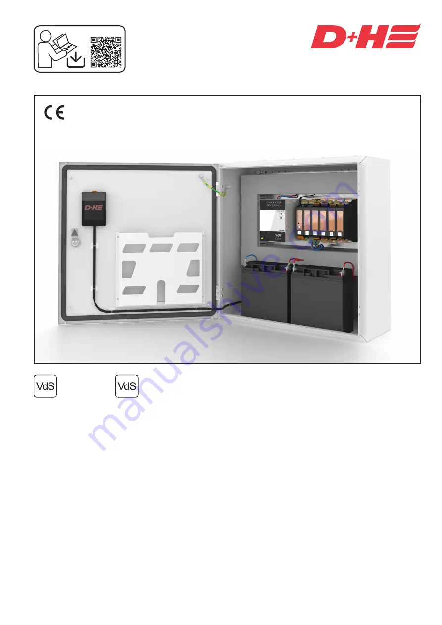
CPS-M1

Anerkennungs-Nr.

approval-no.

G 517002

0786 - CPD - 50680

EN 12101-10:2005 + Corr. 1:2007

conform

99.827.31 2.3/08/22

en

  Original instructions ..............................................Page ............................................................2 

Содержание CPS-M Series

Страница 1: ...D H Downloads CPS M1 Anerkennungs Nr approval no G 517002 0786 CPD 50680 EN 12101 10 2005 Corr 1 2007 conform 99 827 31 2 3 08 22 en Original instructions Page 2 ...

Страница 2: ...wed to connect the power Keep children away from the controller Only use in dry spaces Only intended for installation indoors Only use unaltered D H original parts Important regulations It is necessary to observe VDE 0833 for danger alarm systems VdS 2221 VDE 0100 for electrical systems DIN 18232 for SHEV systems the provisions of the local fire brigade and of the energy supply compa ny for the ma...

Страница 3: ...CPS M and further D H AdComNet SHEV control system Simple implementation of complex SHEV scenarios High flexibility and expandability Each control panel functions autonomously when the bus connection fails Programming via the D H Service and Configuration Suite SCS No specialised system integrator required Can be carried out by any trained D H partner The control panel can receive firmware updates...

Страница 4: ...bracket optional TP C1 35 RJ12 RJ12 socket C o n t r o l m o d u l e C M B T 1 D 4 P 2 C o n t r o l m o d u l e C M B 1 D 4 P 2 M a i n s s u p p l y m o d u l e P S M 1 2 4 0 4 0 2 4 V D C a c t u a t o r m o d u l e A M 1 2 1 0 2 4 D 6 D 2 2 4 V D C a c t u a t o r m o d u l e A M B 1 2 1 0 2 4 D 4 D 2 2 3 0 V A C a c t u a t o r m o d u l e A M 1 1 0 8 2 3 0 D 4 D 2 A n a l o g u e D i g i t a...

Страница 5: ...6 Ah battery type 6 72 hours of emergency supply time Integrated protection against excessive discharge Temperature controlled charging voltage with external temperature sensor Integrated LED to indicate a fault yellow Two connections for peripherals that are and are not supplied with emergency power Connection using removable spring type terminals Conductor cross sections max 2 5 mm flexible or f...

Страница 6: ... outputs The digital inputs can also be parameterised as LT inputs Integrated LEDs to indicate a fault yellow and alarm red Connection using removable spring type terminals Conductor cross sections max 1 5 mm flexible Dimensions WxHxD 26x130x125 mm Installation on a 35 mm top hat rail in combination with an expansion module socket Actuator module AM 1 1 08 230 D4 D2 Module for connecting 230 V AC ...

Страница 7: ...ort circuit resistant YES Can be connected in parallel YES Reverse voltage protected YES Input line connection max 6 mm star max 4 mm flexible Output line connection max 6 mm star max 4 mm flexible Dimensions WxHxD 90x130x150 mm Type PS S1 24 40 Rated input voltage 230 V AC 15 Frequency 45 to 65 Hz Nominal power 1040 VA 960 W Output voltage 24 V DC 1 Ripple 50 mVss Output current 40 A Short circui...

Страница 8: ...ry type 5 12 V 18 Ah 15 For each PS S1 24 40 PSM 2 x battery type 6 12 V 26 Ah 15 A special battery calculator is available for the exact determination of the required battery capacity 24 V emergency supply Components Approx Ah required for 72 hours Intrinsic consumption by CM CM B 0 52 Ah CM CM B supply of the modules 0 018 Ah per module PSM 0 29 Ah IOM 0 26 Ah BRM 0 21 Ah TMA 0 58 Ah AM AM B 0 4...

Страница 9: ...ht of it Each additional PSM always provides power only to the modules to the right of it This applies also to the emergency battery power Therefore the modules are to be distributed evenly across the PSM modules Due to the higher current consumption and shorter cable paths the AM 24 modules are each to be used first next to the PSM module The total current of the drives respectively connected to ...

Страница 10: ...s for supplying the drive Mot a Mot b For pole changing drives 1 additional wire for cable monitoring through which the SHEV high speed HS signal is also transmitted to the drive For ACB drives 2 additional wires for the bus connection Cross section mm cable length m x total current 80 Wind rain sensor SHEV control panel External control SHEV operation panel Approx 1 5 m above upper edge of finish...

Страница 11: ...PE Connection PSM RJ12 connecting cable CC TP TCSU max 2 m Battery Battery No Name Description X2 1 N Output potential without an emergency supply for ventilation functions max 500 mA X2 2 Reference potential do not connect to P X2 3 Output potential with an emergency supply max 500 mA X2 4 Reference potential do not connect to P X4 TCSU1 RJ12 connection of external battery temperature sensor X5 1...

Страница 12: ...face X5 2 ACN D X5 3 ACN D X6 5 n c n c X6 4 DI 1 2 Freely configurable digital input 0 to 28 V active minus or plus control panel OPEN factory setting can be pro grammed using SCS X6 3 DI 1 3 Freely configurable digital input 0 to 28 V active minus or plus control panel CLOSED factory setting can be programmed using SCS X6 2 DI 1 4 Freely configurable digital input 0 to 28 V active minus or plus ...

Страница 13: ...y type Lithium cell CR1216 3 Read in parameterization again Termination The AdComNet segment must be terminated with 2 resistors 110 Ω The resistors must in each case be connected at the end of the cable Connections that are not used also have to be terminated Earth the segment shielding once Further top hat rail levels for additional CPS M modules Not for CM B If a top hat rail is not sufficient ...

Страница 14: ...ely configurable digital output 3 4 X3 2 DO 3 3 freely configurable digital output 3 3 X3 3 Reference potential do not connect to P X3 4 DO 3 2 freely configurable digital output 3 2 X3 5 DO 3 1 freely configurable digital output 3 1 X4 5 DI 1 1 freely configurable digital input 1 1 X4 4 DI 1 2 freely configurable digital input 1 2 X4 3 Reference potential do not connect to P X4 2 DI 1 3 freely co...

Страница 15: ...utput 2 COM X3 1 NC 3 Floating output 3 normally closed X3 2 COM 3 Floating output 3 COM X3 3 NO 3 Floating output 3 normally open X3 4 COM 3 Floating output 3 COM X4 4 COM 4 Floating output 4 COM X4 3 NO 4 Floating output 4 normally open X4 2 COM 4 Floating output 4 COM X4 1 NC 4 Floating output 4 normally closed X5 4 COM 5 Floating output 5 COM X5 3 NO 5 Floating output 5 normally open X5 2 COM ...

Страница 16: ...utput 3 1 max 50 mA short circuit proof X4 5 DI AI 1 1 freely configurable multifunctional input 1 1 digital 0 28 V active minus or plus analog 0 10 V X4 4 DI AI 1 2 freely configurable multifunctional input 1 2 digital 0 28 V active minus or plus analog 0 10 V X4 3 Reference potential do not connect to P X4 2 DI AI 1 3 freely configurable multifunctional input 1 3 digital 0 28 V active minus or p...

Страница 17: ... 24 V DC X4 ADM DI AI x x 0 10 V DC X4 24 V DC N in out 24 V DC ADM DI x x X6 X5 1 kΩ 3 9 kΩ English 99 827 31 2 3 08 22 either either active plus Separate signal conditioner 64 802 61 active plus active minus active minus Digital inputs Multifunctional inputs programmable using SCS Digital Analog Digitale Ausgänge 24 V DC je max 50 mA Programmierbar über SCS Digital outputs 24 V DC each max 50 mA...

Страница 18: ...CB interface of drive group 2 X3 4 ACB A 2 X4 4 SGI 1 Position transmitter for drive group 1 not yet implemented X4 3 Reference potential do not connect to P X4 2 SGI 2 Position transmitter for drive group 2 not yet implemented X4 1 Reference potential do not connect to P X5 4 DO 2 1 Freely configurable digital output 1 1 max 50 mA NOT CLOSED signal LT 2 X5 3 Reference potential do not connect to ...

Страница 19: ... X2 X3 X6 X5 X4 DI 1 1 DI 1 2 DO 1 1 DI 2 1 DI 2 2 DO 2 1 SGI 2 SGI 1 4 3 2 1 ACB B 2 ACB A 1 ACB A 2 ACB B 1 Mot b 2 Mot a 2 Mot b 1 E HS 1 E HS 2 P Mot a 1 P EM 47 K 2x47kW BK BK OG Mot b ACB a HS Mot b ACB a HS Mot a Mot a Mot b ACB a HS Mot b ACB a HS Mot a Mot a EM 47 K 2x47kW BK BK OG X1 1 X1 4 X2 1 X2 4 X3 1 X3 4 English 99 827 31 2 3 08 22 Termination Each ACB bus has to be terminated 110 ...

Страница 20: ...to P X4 4 ACB Supply of the ACB interface X4 3 ACB A ACB interface of drive group X4 2 ACB B X4 1 SGI Position transmitter for drive group not yet implemented X5 4 DO 1 1 Freely configurable digital output 1 1 max 50 mA NOT CLOSED signal LT X5 3 Reference potential do not connect to P X5 2 DI 1 1 Freely configurable digital input 1 1 0 to 28 V active minus or plus OPEN LT X5 1 DI 1 2 Freely config...

Страница 21: ...ES DI 1 1 DI 1 2 DO 1 1 L L N L E N L N NSV L N PE L L N PE L 230 V AC 50 Hz L N PE ION O OFF ION O OFF before vor avant Battery Service switch off the battery Batterieschalter auf OFF schalten débrancher la batterie ION O OFF L N L N PE 1 2 3 4 5 6 7 8 9 E N L L EM 230 NSV 401 English 99 827 31 2 3 08 22 Drives Drives Connection NSV 401 power supply and D H ACB drives Connection NSV 401 power sup...

Страница 22: ...AC 50 Hz L N PE ION O OFF ION O OFF before vor avant Battery Service switch off the battery Batterieschalter auf OFF schalten débrancher la batterie ION O OFF L N L N PE K1 K2 K1 K2 K1 1 2 3 4 5 6 7 8 9 E N L L EM 230 NSV 401 English 99 827 31 2 3 08 22 Drives Connection NSV 401 power supply and third party drives Shunt motors with capacitor winding must be connected via auxiliary relays K1 K2 L a...

Страница 23: ...K Freely configurable digital output 4 1 max 50 mA X6 5 DO 3 2 A Freely configurable digital output 3 2 max 50 mA X6 4 DO 3 3 S Freely configurable digital output 3 3 max 50 mA X6 3 Reference potential do not connect to P X6 2 DO 4 2 Freely configurable digital output 4 2 max 50 mA X6 1 DO 4 3 Freely configurable digital output 4 3 max 50 mA No Name Description as RM RT lines X1 1 DO 2 3 No functi...

Страница 24: ...7 S 6 A 1 K 2 3 5 T 8 5 R 2 3 bu rd EM L01 5 R 2 3 bu rd EM L01 2 8 3 5 T n c 4 Z 7 S 6 A 1 K OK RT 45 4 Z 7 S 6 A 1 K OK 2 8 3 5 T n c RT 45 OK RT 45 OK SD O 371 FD T 271 SD O 371 FD T 271 rd bu EM L01 rd bu EM L01 X1 1 X1 5 X2 1 X2 5 X3 1 X3 5 X4 5 X4 1 X5 5 X5 1 X6 5 X6 1 English 99 827 31 2 3 08 22 Connection TMA 2 lines RT Line 1 RM line 1 RM line 2 RT Line 2 Last Fire detector First to secon...

Страница 25: ...Z Z 7 7 S S 6 6 A A 1 1 K K OK rd bu EM L01 X1 1 X1 5 X2 1 X2 5 X3 1 X3 5 5 4 3 2 1 5 4 3 2 1 TMA 1 D4 D12 5 5 5 4 4 4 3 3 3 2 1 2 1 2 1 X1 X2 X3 X6 X5 X4 5 4 3 2 1 A S n c n c T K FE Z R FE n c Z S n c n c A T Z K FE R n c n c FE 1kW X1 1 X1 5 X2 1 X2 5 X3 1 X3 5 rd bu EM L01 English 99 827 31 2 3 08 22 Connection TMA parallel connection RT Connection TMA to fire alarm system FAS RT line Trigger ...

Страница 26: ...mum output current of 50 mA The connection is permanently short circuit resistant and the fuse used is self resetting If the output is deactivated the output is open has a high resistance Active negative inputs cannot be switched using the output The output can be supplied with emergency power This is to be taken into consideration in the battery capacity calcula tion FE Functional earth can be us...

Страница 27: ...3 in order to protect the devices F Battery Mode lights up The NSV 401 runs in back up operation AC power supply not present or beyond the tole rance range If necessary the required power will be obtained from the battery bank G Mains OK lights up The NSV 401 runs in mains operation does not light up Mains voltage beyond the tolerance range no mains voltage is present at the input defec tive fuse ...

Страница 28: ... 4 x Art Nr 70 200 05 Typ 5 Same as Long WP18 12 Battery capacity 12 Ah 4 x Art Nr 70 200 00 Typ 4 Same as Long WP12 12 Technical Data Safety Notes Operating voltage 230 VAC Risk of injury from electric shock Only an authorised electrician may connect and work on the NSV 401 The NSV 401 may not under any circums tances be operated without an earthed conductor The mains connection must be in phase ...

Страница 29: ...2 4 4 3 3 2 2 1 1 X1 X2 X6 X5 FES SES DI 1 1 DI 1 2 DO 1 1 L L N L E N L N NSV 1 2 3 4 5 6 7 8 9 EM 230 N E L L 1 2 3 4 5 6 7 8 9 E N L L EM 230 L N L N PE L L N PE L NSV 401 English 99 827 31 2 3 08 22 Connection overview NSV 401 230 V AC 50 Hz Separate power circuit Identify the fuse Do not reverse L N Connect PE Further AM 1 1 08 230 D4 D2 Note All AM 230 connected to an NSV 401 must also be co...

Страница 30: ...ll the enclosed fuse BF1 80A between battery A and battery B WARNING A short circuit may occur if the cover is removed 2 3 1 BF1 80A 12 V 18 Ah 12 V 18 Ah 12 V 18 Ah 12 V 18 Ah BF1 80A 12 V 12 Ah 12 V 12 Ah 12 V 12 Ah 12 V 12 Ah 2 3 1 4 Observe the correct connection order 1 2 3 WARNING Make sure the polarity is correct Battery fail polarity A B 5 The cover must be in place to eliminate the risk o...

Страница 31: ...e used in conjunction with corresponding D H high speed drives If D H drives without high speed or third party drives are connected activation can destroy the drive Standard configurations Controller Module CM The isolated outputs from Controller Module are pre configured by all standard control panels The terminal X1 is for general fault and the terminal X2 for general alarm signals The digital i...

Страница 32: ...y moves in the CLOSED direction in the event of a mains outage Only the control panel groups move in the CLOSED direction in the event of a mains outage Groups in the same link belonging to another CPS M are not affected by this Storage operation OPEN The group moves in the OPEN direction when a ventilation button of the ventilation link is pressed once Storage operation CLOSED The group moves in ...

Страница 33: ...uts IOM I O module Display of the module status Display of the status of the inputs and outputs Modules Overview of all modules used Display of the respective statuses similar to the LEDs on the respective module TMA Trigger module Display of the module status Status display of the lines Switch on and off and resetting the lines Status display of the inputs and outputs BRM Relay module Display of ...

Страница 34: ...ing the smoke vent button as otherwise there is a risk of wind or water damage If gap ventilation is desired in bad weather the weather automation can be switched off using an optional automatic switch If no automatic switch is present gap ventilation is not possible in poor weather If the weather automation is switched on the system closes in case of wind or rain It does not open again automatica...

Страница 35: ...ation Closing after alarm Manual opening with smoke vent button Automatic opening with fire detector Automatic opening through external control e g central fire alarm For manual triggering using smoke vent button Opening the housing control panel and button using the accompanying key When triggered by a fire detector or external control Emergency closing when alarm cannot be reset External control...

Страница 36: ...ystems etc must not be impaired by stored articles or structural changes Maintenance and cleaning Carried out once a year by a specialist company authorised by the device manufacturer Carry out cleaning and maintenance work only when the system is de energised Replace the inspection plate maintain the operational book The inspection and maintenance must take place in accordance with the D H mainte...

Отзывы: