©2008 Cypress Computer Systems,Inc. • www.cypressworld.com 3/4/08
Page 1
MAN-FA-DPX-5500 v1.00
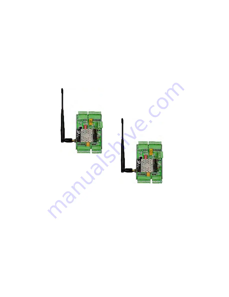
DPX-5500 Series
Wireless Reader Extenders
Operations Manual
Model DPX-5510 Shown
Страница 1: ...2008 Cypress Computer Systems Inc www cypressworld com 3 4 08 Page 1 MAN FA DPX 5500 v1 00 DPX 5500 Series Wireless Reader Extenders Operations Manual Model DPX 5510 Shown...
Страница 2: ...nput Aux Digital I O 1 Output Reader 2 Signals Reader 1 Signals N C Alarm Digital Input Aux Digital I O 3 Input Aux Digital I O 1 Output Aux Digital I O 2 Input Aux Digital I O 2 Input Strike Relay N...
Страница 3: ...1 2 3 4 5 6 7 8 Service Config Mode Reserved Setting 2 3 4 OFF Reader Format Switch 6 7 8 0 1 x 2 x 3 x x 4 x 5 x x 6 x x 7 x x x Wiegand Wiegand No Filter Strobed Rising Edge MR 5 Strobed Rising Edge...
Страница 4: ...s and can radiate radio frequency energy and if not installed and used in accordance with the instructions may cause harmful interference to radio communications However there is no guarantee that int...
Страница 5: ...operate in the same environment without interfering with each other The 1 DIP switch is the Setup Config switch This switch has multiple functions With the switch in the OFF position the unit operate...
Страница 6: ...Specifications Frequency 900 MHz ISM band Type Frequency Hopping Spread Spectrum Transmit Power 100mW Receive Sensitivity 110 dBm Interference Rejection 70dB Antenna Options and typical range Interna...
Страница 7: ...sible at the same time It is also a chance to become familiar with the system if this is the first time using the Duprex system It is much more difficult to configure and test the units when they are...
Страница 8: ...de This switch change can be made at any time When the switch position is changed the unit will reset and restart in the new mode This is helpful for setup and diagnostic purposes In Normal operationa...
Страница 9: ...c LED should illuminate a solid red color Plug in the Central unit power supply The Green power LED should illuminate The Amber com LED should flash and then go out After a short delay the Diagnostic...
Страница 10: ...o the Duprex units Remember to disconnect any power supplies if you will be using the panel power supply or other auxiliary supply Only one power supply should be used for each unit Connect the Centra...
Страница 11: ...gth dimension of the antennas are in the same plane The orientation of the antenna will determine what is referred to as the polarization of the signal Significant reduction in range can result if the...
Страница 12: ...imum signal and ranges are achieved when the antenna is clear of obstructions and is placed away from metal objects This orientation may reduce range The metal pole is placed between antenna and other...
Страница 13: ...ome installations it may be easier to use these knockouts Screw knockout Knockout removed by pressing on it with screwdriver blade Be careful not to damage interior components Screw placed in knockout...
Страница 14: ...crews Four mounting screws can be threaded through the corner holes This also is advantageous in that the screws do not breach any of the environmental seals Mounting screws are not included due to th...
Страница 15: ...Config mode Once operation has been verified in Service Config mode then the units can be placed in Normal Run mode The Amber com LED will flash infrequently in Normal mode It should flash each time...