CY3668 W
IRELESS
USB™-NL
DEVELOPMENT KIT
QUICK START GUIDE
2
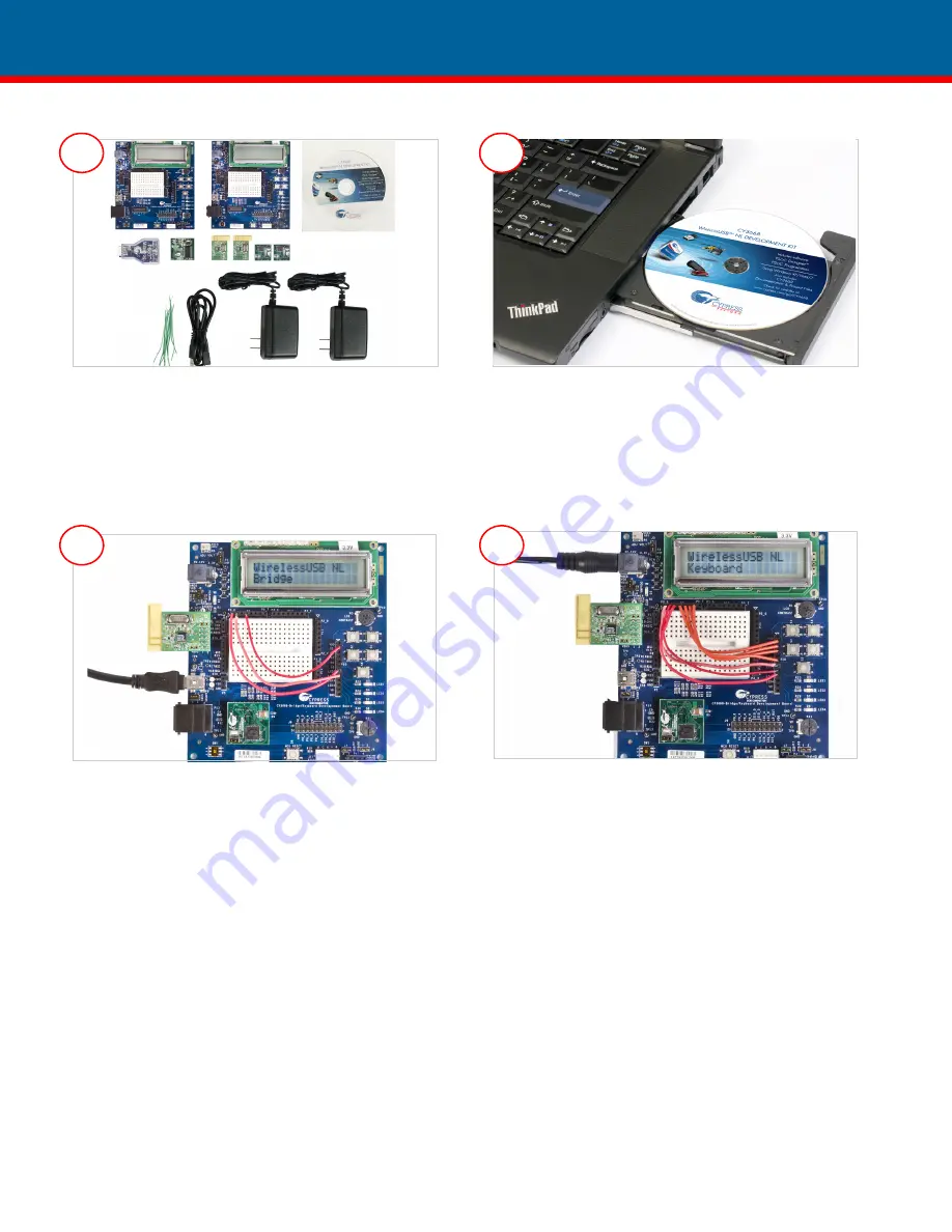
The CY3668 DVK consists of two development boards, two
WUSB-NL Radio modules, one enCoRe II module, two enCoRe V
modules, one MiniProg, two 12-V power adapters, one USB A/
Mini-B cable, one CD, and 10 jumper wires.
Note:
When you receive the kit, ensure that the enCoRe V modules
are connected on the development boards.
• Insert the CY3668 kit CD into the computer’s CD drive.
• If the WirelessUSB-NL DVK installer application does not launch
automatically, launch it manually by clicking 'cyautorun.exe'.
• Click
Install WirelessUSB NL DVK
to install PSoC Designer,
PSoC Programmer, and WirelessUSB-NL DVK software.
Key instructions for programming Bridge and Keyboard
•
Do not
attach the WUSB-NL module to development boards.
•
Do not
attach any power source (AC-DC adapter or USB
cable) to development boards.
Setting up the Bridge
• Program one of the development boards with the Bridge firm-
ware that is located at
<Install_Directory>\
Cypress\CY3668 DVK\1.0\Firmware\Bridge\
NL_Bridge_enCoReV\
NL_Bridge_enCoReV\
NL_Bridge_enCoReV.hex. See the user guide for the program-
ming procedure.
Note
: The default install directory is "C:\Program Files" or
"C:\Program Files (x86)"
• Attach the following wires from P7 to P10: P0_3 to S1, P0_0
to LED1, and P0_1 to LED2.
• Plug in the WUSB-NL module on the development board
• Connect the Bridge to the computer using the USB cable
If the LCD panel text is not visible, increase the LCD contrast by rotat-
ing the knob located below the LCD panel in clockwise direction.
Setting up the Keyboard
•
Program the other development board with the keyboard
firmware located at <Install_Directory>\Cypress\ CY3668
DVK\1.0\ Firmware\ Keyboard\ NL_Keyboard_enCoReV\
NL_Keyboard_enCoReV\NL_Keyboard_enCoReV.hex. Use
the same procedure as for the Bridge.
•
Attach the following wires from P7 to P10: P0_3 to S1, P0_4 to
S2, P0_5 to S3, P0_6 to S5, P0_0 to LED1, P0_1 to LED2, and
P0_2 to LED3.
•
Plug in the WUSB-NL module on the development board.
•
Power the keyboard using the 12-V power adapter.
Establish Wireless Link and Data Transfer
•
Press and release S1 on the Bridge to change to Bind mode.
LED1 on the Bridge blinks to denote Bind mode. Press and
release S5 on the Keyboard to change to Bind mode; wait for 2
seconds. On successful binding, LED1 on the Bridge switches off
and the wireless link is now ready for data transfer
•
On the Keyboard, press and release S1 for Num Lock, S2 for
Caps Lock, and S3 for Scroll Lock. The actions corresponding to
the pressed key are executed on the computer.
1
2
3
4


