background image

29/38

S

ept

.


2014  

V3.1

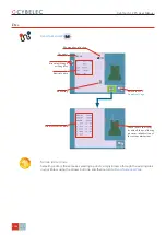
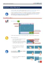
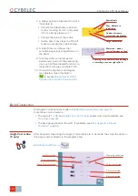
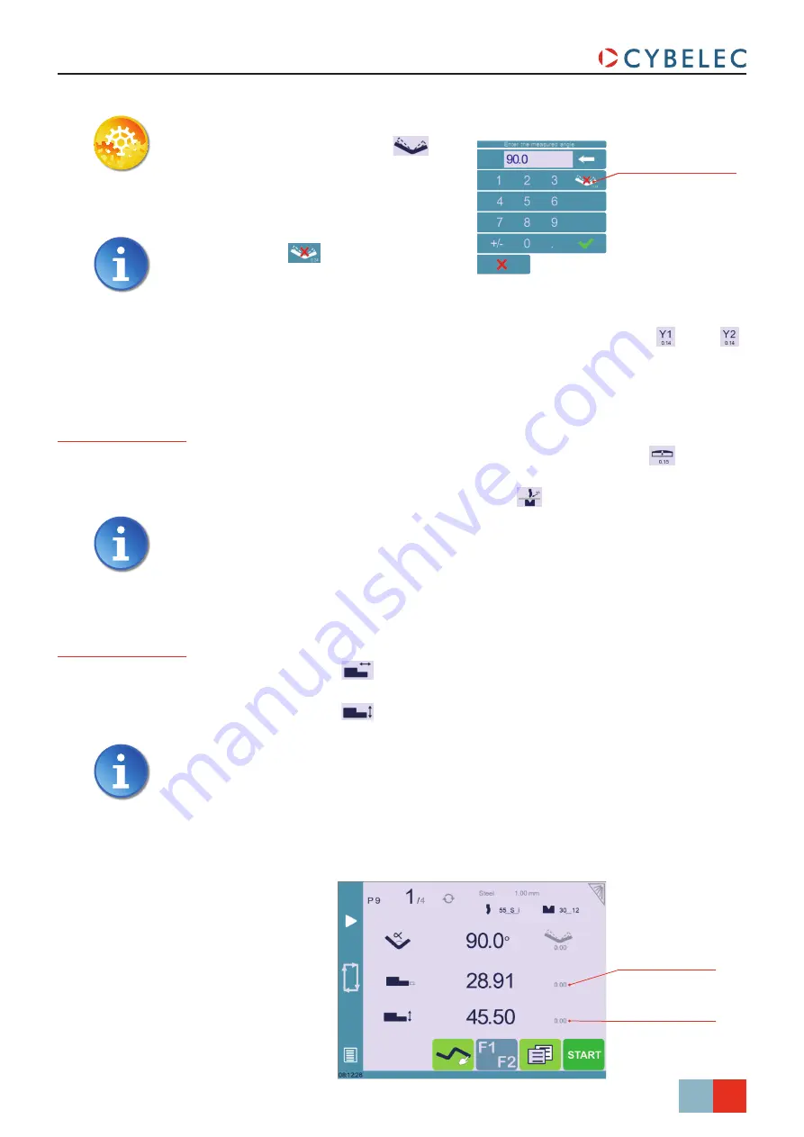
Back gauge (X axis) 

position correction value

Back gauge (Y axis) 

height correction value

CybTouch 12 PS User Manual

Crowning

Reset corrections button

S

etting

 i

nStructionS

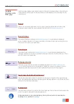
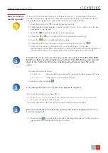
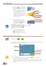
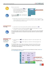
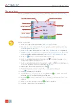
1.  Touch the angle correction 

 icon, 

and enter the physically measured 
value of the angle. The numerical 
control will automatically calculate the 
Y1 and Y2 axes corrections. 

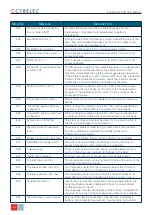
Pressing this 

 button will reset all 

angle corrections.


2.  Depending on the position of the sheet metal in the press, it may be necessary to 

fine-tune the beam’s corrections. It is possible by simply touching this 

 or this 


icons, and entering the desired values.

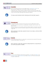
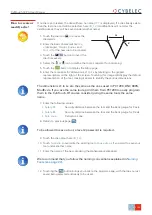
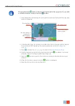
3.  Corrections to the crowning value can be made by touching this icon 

.

4.  The numerical control automatically calculates the Pinch Point height. If it needs 

correction, it can be done by touching this icon 

.

The grayed value next to the Pinch Point correction icon is the value calculated 
by the numerical control, and thus the value onto which the correction will be 
applied. 

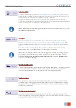
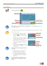
Back gauge 
(X & R axes) 
Correction

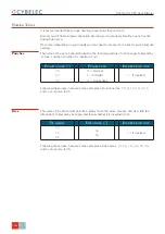
5.  Touching this icon 

 allows applying a correction to the back gauge X axis 

position.

6.  Touching this icon 

 allows applying a correction to the back gauge R axis 

position.

The grayed values next to the back gauge correction icons are the value 
calculated by the numerical control, and thus the values onto which the 
corrections will be applied.

The back gauge positions corrections can also directly be made on the 

Bend 

Numerical Page (see page 14)

.

Reset corrections button
Содержание CybTouch 12

Страница 1: ...User Manual for Synchronized Press Brakes Sept14 V3 1 ...

Страница 2: ...c S A All Rights Reserved Copying reproduction modification distribution display or transmission of any of the contents of this manual for any purpose without the prior consent of Cybelec S A is strictly prohibited ...

Страница 3: ...g started with CybTouch 12 3 General navigation 4 Menu Button 4 Status Pages Zone 4 Screen Cleaning 4 Status page 5 User Preferences 5 Language 6 Length Units 6 Show Y1 Y2 position values 6 Show page L alpha num 6 Show bent part 6 Materials 7 BDC correction 7 Clear indexation 8 USB Explorer 8 Default retraction 8 Set Clock 8 Touchscreen Calibration 8 Brightness xx Eco xx 9 ...

Страница 4: ...2 Computer ID 12 Option list 12 New option code 12 USB Transfer 13 Importing parts from other Cybelec NCs 13 Basic Page Description 14 Bend Numerical Page 14 More Page 14 Available functions on the More page 15 Material 15 Material thickness 15 Material sigma 15 Back gauge retraction 15 Speed change threshold and bending speed 15 Bending length 15 Step bending 16 Slow speed return 16 Dwell time 16...

Страница 5: ... or modify a die 21 Naming Tools 22 Punches 22 Dies 22 Creating a Part Program 23 TouchProfile Mode 23 Automatic Bend Sequencing optional 24 Numerical Mode 26 L Alpha Mode 27 Bend Correction 28 Angle Correction Y axis 28 Crowning 29 Back gauge X R axes Correction 29 Saving and Loading a Program 30 Saving a Program 30 Loading a Program 30 Deleting a Program 30 EasyBend Page 31 Making a bend on the ...

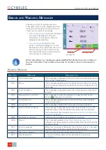
Страница 6: ...The Intuitive Programming Error and Warning Messages 32 Warning Messages 32 Error Messages 35 ...

Страница 7: ...The Intuitive Programming ...

Страница 8: ...The Intuitive Programming ...

Страница 9: ... numerical control is installed Improper use of the numerical control can cause heavy damage on equipment and or injuries to people Modification of machine parameters can cause important material damage or lead to irregular product quality Do not expose the numerical control to excessive humidity so as to avoid any risk of electrocution and any deterioration of the equipment Make sure the numerica...

Страница 10: ...pay attention to rules instructions or advice The correct sequence of operations is to be followed in order to avoid damage to the machine Symbolizes a serious personnel danger This warning sign appears in this manual whenever an important information needs to be taken into consideration Pay attention to this sign and follow the instructions given This sign appears in this manual whenever setting ...

Страница 11: ...ess down hard on the screen Pressing hard on the screen will damage the display Such damage is not covered by manufacturer warranty Do not use sharp and or pointed objects sheet metal screwdriver metal pen ball etc to touch the screen only use your fingers with or without gloves on or a plastic pen Make sure that your gloves do not have metal particles encrusted in the finger tips as they may also...

Страница 12: ...sired screen The content of the menu changes contextually The Status pages zone gives access to the Status page see page 5 This is really a zone that is active at any moment from any page except the wizard s Screen Cleaning To clean the screen while the CybTouch is on touch the button Use only a damp and smooth cloth with soap or a neutral detergent Status Pages Zone NEVER use solvent petrol benze...

Страница 13: ...rence User Preferences The Status page shows the status of all inputs and outputs and axes positions of the NC This feature is very useful during setup or during phone service with a machine installed in the field This page is accessed from anywhere by pressing the Status Pages Zone see page 4 To exit the Status page press on the arrow on the left Status page To exit the User Preference page touch...

Страница 14: ...splayed under the angle beam s position line EN English BR Brazil CN 中文 CZ Český DE Deutsch ES Español FR Français IT Italiano The list of available languages is subject to change and may increase over time Length Units This parameter allows choosing between mm inch and none for the length unit to be used in the CybTouch Show page L alpha num When set to yes this parameter gives access to the L Al...

Страница 15: ...in max determines the maximum and minimum accepted thickness for the selected material Three predefined default materials are available steel stainless steel aluminum but others can be added To add a material 1 Touch Material and select a non configured material Mater X from the list 2 Enter the new material s characteristics 3 Touch the name Mater X to display the keyboard and enter the name of t...

Страница 16: ...allowing the operator to re index its machine without turning it off Default retraction This parameter allows defining the default value displayed in the More Page see page 14 when activating the back gauge retraction function Touchscreen Calibration As a tall operator will tend to touch higher than a smaller one on the screen this function allows the calibration of the touch screen and also makes...

Страница 17: ...enus Manual movement Setting Instructions 1 Select the axis that you want to move for the back gauge X axis for the back gauge R axis for the crowning axis 2 Touch the buttons to move the selected axis 3 Use the foot switch Low Speed Down movement and this button High Speed Up to move the beam In the course of setting up a machine it is sometimes necessary to be able to move the axes manually for ...

Страница 18: ...page displays the hardware status of the CybTouch and lets the operator perform different maintenance actions All the following actions require codes and should only be performed by technicians or upon request of a technician Menu Button Other menus Service Service Maintenance This function must be used with utter care and only by experienced personnel Wrong settings may mechanically damage the ma...

Страница 19: ...s with the help of a technician Internal backup This function is specially designed for OEM and support Usually a machine parameters backup is made by the machine manufacturer or the company who services the machine This backup allows a maintenance technician to restore original working parameters if necessary Should there be a need to restore parameters call on a maintenance technician and follow...

Страница 20: ...tup and is related to the machine s option list Changing the serial number means that all the options installed on the machine can be lost Computer ID This line displays an identification code that is unique to each CybTouch and guarantees together with the serial number a correct identification of the machine Option list This function opens a yellow pop up window where all the options installed o...

Страница 21: ...er This function opens the USB transfer screen which allows the operator to transfer data between the CybTouch and a USB key CybTouch 12 is delivered with Cybelec s off line software PC1200 which controls most of the other numerical controls produced by Cybelec From version S1 PC1200 includes CybTouchConverter which allows you to convert parts to the CybTouch format and import them into your machi...

Страница 22: ...ition flange length Add step or next step Program number Current step sequence number Repeat sequence button inactive here Material thickness Material sigma Bending length Force Back gauge manual control Return to Bend Numerical Page Crowning Opening TDC Dwell time Speed change threshold and bending speed LazerSafe Back gauge finger type Step bending Slow speed return Number of parts Back gauge re...

Страница 23: ... is automatically displayed when changing material It is however possible to change it simply by touching this icon This is also of course a part parameter Back gauge retraction The back gauge retraction can be activated deactivated at its Default retraction see page 8 value using this icon It is possible to modify the value by touching it This is a sequence parameter meaning it can be modified wi...

Страница 24: ...automatically calculate the maximum possible step bends The resulting value may be reduced However if it is increased over the maximum calculated value the resulting radius and angle will be drastically affected Dwell time Allows defining the duration of the dwell time meaning the time during which the punch remains at BDC before coming back up Force The force is automatically calculated by the Cy...

Страница 25: ...e machine parameters It can however be programmed here Creating a New part reinitializes it to its default value Crowning The crowning function is activated here It is automatically calculated according to the Material the Material thickness the Material sigma and the Bending length If the crowning needs correction use the Crowning see page 29 function in the correction page The value can be manua...

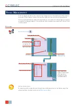
Страница 26: ...ools management allows the creation and configuration on the CybTouch of the tools to be used on the machine These tools are then taken into account in bend calculations Once a punch and die are created and selected you can select the bend angle you require as well as the flange length L The CybTouch then calculates the positions for axes X and Y for the bend Punches Bend Numerical Page Setting In...

Страница 27: ...ching this image will display the default representation of the tool making it easier to identify the various dimensions The dimensions L1 to Lx are the same as the ones used in PC 1200 DNC 880S ModEva s If you use the same tools print them from PC1200 to easily program them in the CybTouch Of course consider giving the same tools the same name 8 Enter the following values Safety XS Security dista...

Страница 28: ... Die name Touch the die to display its default shape allowing an easier identification of the various dimensions CybTouch 12 PS User Manual Dies Bend Numerical Page Setting Instructions Selecting a die is the same as selecting a punch simply browse through the existing dies in your library using the arrows buttons and then return to Bend Numerical Page ...

Страница 29: ...e tool making it easier to identify the various dimensions The dimensions L1 to Lx are the same as the ones used in PC 1200 DNC 880S ModEva s If you use the same tools print them from PC1200 to easily program them in the CybTouch Of course consider giving the same tools the same name 7 Enter the following values Safety XS Security distance between the tool and the back gauge for X axis Safety RS S...

Страница 30: ...er first its angle followed by its type and then whether it is inverted or not The name of the die should be built in pretty much the same manner first its width Ve dimension followed by its angle and then whether it is inverted or not Following these rules here are some examples of punch names 90_N_i 60_G 30_S and so on and so forth Following these rules here are some examples of die names 12_86_...

Страница 31: ...n very intuitively draw a profile directly on the screen Setting Instructions 1 Touch the program number and select New program in the list 2 First select the material its thickness and the tools to be used for the part by touching their respective icons 3 Draw the profile by touching the screen where you want to add a segment Touching this icon allows erasing the last segment added 4 Touch on the...

Страница 32: ...the CybTouch Bend Numerical Page Setting Instructions 1 Simply touch the bend sequence calculation button Once the sequence is calculated the Bend 2D screen is displayed 2 If the option is not installed simply touch the bend in the order that you want them performed A small number is displayed on the bend indicating its position in the sequence 5 Touch on an angle to modify its value Touching the ...

Страница 33: ...Bend 2D screen here below is displayed 4 In the Bend 2D page the operator must determine the back gauge and part position for each bend and if necessary the special parameters on the More Page see page 14 5 Press and select Bend num page to return to the Bend Numerical Page 6 Start the hydraulic pump motor by pressing this button if available It turns red when the motor is running the button becom...

Страница 34: ...ness the Bending length and other sequence parameters Opening TDC Slow speed return etc 5 Touch the button to return to the Bend Numerical page 6 Touch the numerical value next to the angle icon and enter the value for the first bend you wish to create here 90 7 Touch the numerical value next to the segment length icon and enter the value for the first segment you wish to create here 30 00 mm 8 Ad...

Страница 35: ...ha mode 2 First select the material its thickness and the tools to be used for the part by touching their respective icons 3 Touch the first value in the table here 200 00 The window to the right is displayed 4 Enter the value for the first segment s length and touch the button to add another step Click on OK when prompted to create new step 5 Proceed in the same manner for all steps and angles of...

Страница 36: ...teps to execute the step bending Large radius value Touching a step number allows deleting it or inserting a new one right after it 7 A yellow pop up is displayed in which it possible to Activate and deactivate a special tool by touching its icon and select it from a list by pressing Change the value of the radius Define how many steps the NC will make to execute the step bending 8 A small More ic...

Страница 37: ...ning value can be made by touching this icon 4 The numerical control automatically calculates the Pinch Point height If it needs correction it can be done by touching this icon The grayed value next to the Pinch Point correction icon is the value calculated by the numerical control and thus the value onto which the correction will be applied Back gauge X R axes Correction 5 Touching this icon allo...

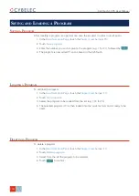
Страница 38: ...owed by 4 The program is now called P1 and is saved in the CybTouch Loading a Program To call load a program 1 In the Bend Numerical Page touch the Program number ex P1 2 Touch Call program 3 Select the program to be loaded from the list e g 002 for P2 4 The selected program P2 is then loaded into the work memory and is ready to be used Deleting a Program To delete a program 1 In the Bend Numerica...

Страница 39: ...Steel The More Page see page 14 is displayed Select the Material see page 15 used enter the Material thickness and the Bending length 2 Touch one of the tool s icon or to select a punch or die To learn how to configure tools please refer to section Tools Management page 18 3 Enter the angle for the first bend you wish to create here 90 4 Enter the flange s length here 100 00 mm 5 Enter the back ga...

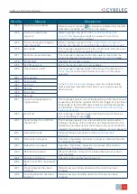
Страница 40: ...ed W04 Please press 2 seconds This message reminds the operator to keep the start pump button pressed for 2 seconds W05 The pump is on This message appears after the pump starting cycle has been correctly executed W06 The pump is off This message indicates that the pump has been stopped W07 Select at least one bend This message is displayed when the operator tries to go to the Bend 2D screen from ...

Страница 41: ... Set day W25 Set month W26 Set year W27 Touch the small graphic to toggle screen This message appears once at the beginning of the bend manual sequencing telling the operator that he can toggle from the Bend Order page to the Bend 2D page simply by touching the graphic at the bottom of the screen see Automatic Bend Sequencing optional page 24 W29 End of list This message is displayed when reaching...

Страница 42: ...k HMI is set to yes and the screen is touched W46 Enter password level 1 or greater This message is displayed when a password of level 1 or higher is needed to execute a specific operation W47 Enter password level 3 This message is displayed when a password of level 3 or higher is needed to execute a specific operation W48 Enter new password These messages are displayed when changing passwords W49...

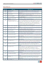
Страница 43: ... is missing E11 Write to file problem This file is corrupt and cannot be saved Try to restart the NC If the problem persists format the memory E12 X under minimum limit Operator entered a value under the limit or a memorized value in the program is under the limit The wrong value flashes and must be corrected E13 X over maximum limit Operator entered a value over the limit or a memorized value in ...

Страница 44: ...operly E32 Crowning analog output not configured While configuring setting up the NC the Crowning dedicated outputs were not configured but are requested to run properly E33 Syntax error in XML file This file is corrupt and cannot be used Try to restart the NC If the file is a part program try to delete it E34 Memory allocation problem xml There was a problem while trying to read a file in the mem...

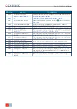
Страница 45: ...oscillations Not enough oscillations Increase the identification time See machine parameters manual E57 Identification Error 3 Amplitude of the oscillation Oscillation amplitude Increase the identification voltage See machine parameters manual E58 Fw Axes Error 32 Trajectory tracking error This is a regulator error The axis could not follow its trajectory This may be due to high friction resistanc...

Страница 46: ... would cause a collision between the back gauge and the tools Check your parameters values E74 Beam error No E75 Beam static gains not found E76 Error in the parameter beam you must correct it before continuing E77 Error in the sequence parameter you must correct it before continuing E78 RS232 parity error E79 RS232 overrun E80 RS232 framing E81 RS232 noise E82 PCSS event No xx E83 PCSS error time...

Отзывы: