


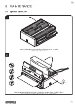


6.8 Alignment parameters
The device allows the coniguration of the parameters listed in the following table.
The parameters marked with the symbol
D
are the default values.
Settings remain active even after the device has been turned off and they are stored in non-volatile memory.
BLACK MARK
Alignment management:
Disabled
D
= the black mark alignment is not performed
Enabled
= the black mark alignment is performed
BLACK MARK
THRESHOLD
Threshold value (in percent) for the recognition of the presence of black mark by the
black mark sensor:
30% 50% 70% 90%
40%
D
60% 80%
If the “Black Mark” parameter is disabled, this parameter is not printed.
BLACK MARK DISTANCE
"Black Mark Distance" is the minimum distance (expressed in millimetres) between the
upper edge of ticket and the black mark (see
).
If the “Black Mark” parameter is disabled, this parameter is not printed.
The numeric value of the distance is made up with the following four parameters for the
setting of three digits (two for the integer part of the number, one for the decimal part
and of the sign):
BLACK MARK DISTANCE SIGN
Sign setting:
+
D
=
positive distance
- =
negative distance
BLACK MARK DISTANCE
[mm x 10]
Setting the digit for tens:
0
D
1 2
BLACK MARK DISTANCE
[mm x 1]
Setting the digit for units:
0
D
2 4 6 8
1 3 5 7 9
BLACK MARK DISTANCE
[mm x .1]
Setting the digit for decimals:
0
D
2 4 6 8
1 3 5 7 9
NOTES:
For example, to set the black mark distance to 15 mm, modify the parameters as follows:
Black Mark Distance sign
= +
Black Mark Distance [mm x 10]
= 1
Black Mark Distance [mm x 1]
= 5
Black Mark Distance [mm x .1]
= 0
Values for “Black Mark Distance [mm x 1]” > 5 can be set only if “Black Mark Distance
[mm x 10]" = 0 o 1.
64
Содержание KPM216HIII
Страница 1: ...USER MANUAL KPM216HIII ...
Страница 2: ......
Страница 4: ......
Страница 6: ......
Страница 10: ...10 ...
Страница 12: ...12 ...
Страница 22: ...22 ...
Страница 29: ...2 3 Remove the side cover Fix the brackets as shown in figure Observe the orientation of the slot A 29 ...
Страница 66: ...66 ...
Страница 74: ...74 ...
Страница 93: ...127 140 5 140 5 74 8 147 4 83 30 5 196 24 5 5 24 5 5 159 48 270 1 6 16 5 16 5 12 5 12 5 12 93 ...
Страница 100: ...100 ...
Страница 102: ...102 ...


