


2 — INSTALLATION SPECIFICATIONS AND WIRING
Curtis Model 1351 – December 2018
pg. 18
Digital (driver) Outputs
The three digital outputs are low-side drivers with a 3-ampere current (sink) limit. As low-side drivers,
they can only be turned ON or OFF. The control modes for PWM, constant current or voltage are not
available. For inductive loads, these drivers have a fly-back diode to Coil Return. Resistive loads must
not exceed the 3-amp current-sink rating. The VCL function
Digital_Out_X_Command
(where X is 1,
2 or 3) or
Put_Driver()
is used to control these drivers (where a non-zero value = ON).
Digital Output 1 can also be used as either the Encoder 2B or analog1 inputs, based upon parameter
settings. The Digital Outputs 2 and 3 parameters can be disabled for use as digital switch inputs
(Switches 11 and 12 respectfully).
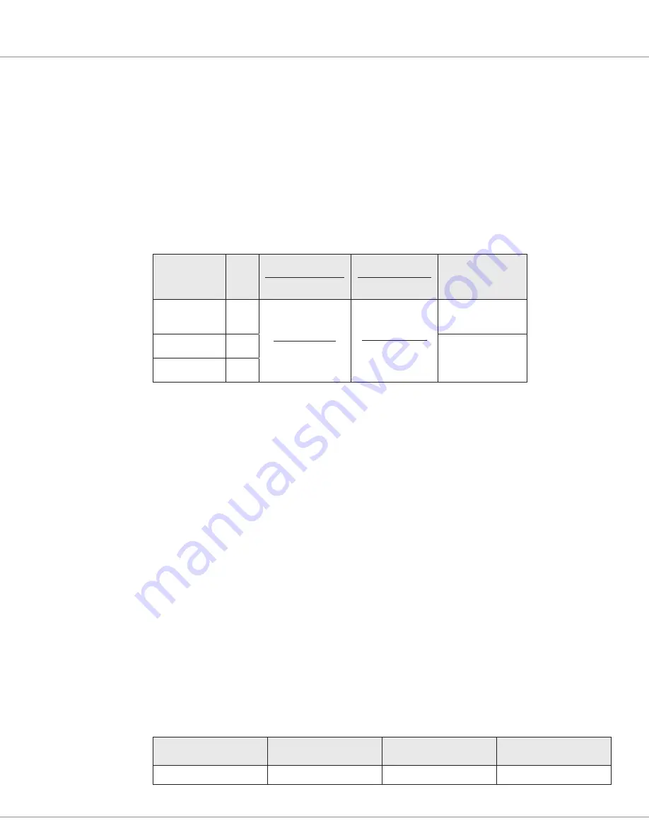
Table 6 Digital Outputs (drivers) Electrical Specifications
Signal Name
Pin
Output Type
Activity Level
Output Current
Short-Circuit
Input Impedance
(Off State)
Digital Out 1
1
Low-side Driver
On/Off
3 Amps
(100% On)
< 30 Amps
for < 100μS
> 350kΩ
Digital Out 2
25
> 650kΩ
Digital Out 3
34
Safety Output
The Safety Output provides the power to all connected loads. The safety output must be enabled for
the connected drivers to operate. The Safety Output is normally used as the Coil Return connection
for low-side driver loads, but it can also be used as a high-side driver for a safety/system contactor.
Once enabled, the safety output can supply up to 23 amps of B
+
voltage at the pins (in common) 11
and 12 (
see the Safety Output Command parameter
).
The system designer shall ensure the driver loads at pins 11 and 12 are under the combined 23-ampere
current rating. The safety output will shut down if excessive over-current or a short is detected.
Analog Output
The system controller has one analog output. This adjustable 0-10V Op Amp output is intended
to drive high-impedance loads, such as a battery discharge indicator or hour meter. This output is
generated from a filtered PWM signal and has about 1% ripple. The 2% settling time is <25 ms for
a 0–5 V step and <30 ms for a 0–10 V step. This output line is protected against shorts to B
+
or B
−
.
The analog output is parameter settable, sharing the output with the Analog 11 input (pin 22).
Set the output voltage by setting the VCL variable
Analog_Out_Command
from 0–1000 (0.00 to
10.00V).
Table 7 Analog Output Specifications
Signal Name
Pin
Output Voltage
Output Current
Analog Out
22
0 to 10 V
10 mA


