background image

Part No. 4801-5331 Rev 2-2015 

Owners Manual 

Evolution 1200 


CUMBERLAND            

Assumption, IL 62510         

• Phone 1-217-226-4421           • Fax 1-217-226-4420


Evolution 1200 

Environmental Controller


Cumberland 

Date: 05-18-15                                                                                  1004 E. Illinois St.


                                                                                                 Assumption, IL 62510


Controller Software Version V0.37


Содержание Evolution 1200 Series

Страница 1: ...rs Manual Evolution 1200 CUMBERLAND Assumption IL 62510 Phone 1 217 226 4421 Fax 1 217 226 4420 Evolution 1200 Environmental Controller Cumberland Date 05 18 15 1004 E Illinois St Assumption IL 62510...

Страница 2: ...l Ventilation Stages 15 6 4 4 Variable Stages 16 6 5 Historical Data 16 6 5 1 Room Temperature 16 6 5 2 Humidity Sensor 17 6 5 3 Water Usage 1 or 2 17 6 5 4 Ventilation Mode 17 6 5 5 Feed History 18 6...

Страница 3: ...itor to Evolution 1200 45 8 5 Connecting Humidity Sensor to Evolution 1200 45 8 6 Connecting PC Network to Evolution 1200 46 8 7 Connecting Alarm Device to Evolution 1200 46 8 8 Connecting Water Meter...

Страница 4: ...ons and Limitations THERE ARE NO WARRANTIES THAT EXTEND BEYOND THE LIMITED WARRANTY DESCRIPTION SET FORTH ABOVE SPECIFICALLY GSI MAKES NO FURTHER WARRANTY OF ANY KIND EXPRESS OR IMPLIED INCLUDING WITH...

Страница 5: ...eating and ventilation system where failure could result in loss or injury the user should provide adequate back up or accept the risk of such loss or injury 3 Ratings and Specifications HHI Part Numb...

Страница 6: ...evel Inputs 6 PowerTrak auxiliary switch inputs 1 static pressure transducer Optional HHNet connection for PC compatibility Output Devices Standard 8 On Off output stages with manual override switches...

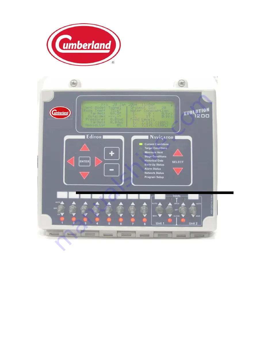
Страница 7: ...in Display screen The arrow buttons are used to scroll to variables that appear within the current screen of the Main Display The plus and minus buttons are used to change or modify a variable s value...

Страница 8: ...PONENTS OR WIRES 5 4 Inlet Stages Optional inlet stages may be added to control vents curtains Up to 2 inlet stages may be added per controller unit When Auto Manual toggle switch is placed in Auto po...

Страница 9: ...arked on the front panel For optional Variable Stages 7 8 use stick on V1 V2 label placed over stages 7 8 numbers Stage number Use V1 V2 label over Stages 7 8 if Stages 7 8 are used for Variable Outpu...

Страница 10: ...creen can only be unlocked using the HHI Service Code Contact your local dealer for assistance 6 Viewing Navigator Status Screens The following nine screens are available Current Conditions Target Con...

Страница 11: ...are shown below The specific Target Conditions screen features and setting options will depend on whether Optimum Mode is ON or OFF Examples and details for both the Standard screen and Optimum scree...

Страница 12: ...t day The Run is the percentage of the Minimum Timer Cycle that the stage will run 4 Adjust Adjusts the programmed Optimum Run by this amount until set otherwise The displayed Optimum Run to the left...

Страница 13: ...will start the vents open before a stage comes on 6 Variable Speed These settings are used to set up variable speed fan operation 7 V1 Minimum The minimum speed or minimum percentage of light intensit...

Страница 14: ...the up and down arrows in the Editor to view the desired information Notice that the Light Clock and Feed Clock Stages are listed after the Inlet Conditions section The Heat Stages are then displayed...

Страница 15: ...the stage is programmed Any stage can be set to any of these modes The available stage options are Off Heat CSTIR CNEG CNEGT CTUN LIGHT FEED or CEVAP 4 Rtemp The Rtemp column will indicate the curren...

Страница 16: ...rating 5 ON The ON column indicates the maximum ON temperature at which the variable speed fan will reach full speed 6 OFF The OFF column indicates the minimum ON temperature at which the fan will run...

Страница 17: ...of day that it occurred 3 Total For Each Day The total water usage for each day of growout 6 5 4 Ventilation Mode This screen shows the length of time in hours and minutes that the Control is in diffe...

Страница 18: ...screen shows the length of time in hours and minutes that the individual stages have run on the current day and previous day 1 Stage Identifies the stage number 2 Current Day The length of time in hou...

Страница 19: ...up High Limit The high temperature limit at which the Back up stages will start turning on cool stages 2 Target Temperature Backup target temperature 3 Back Up Low Limit The low temperature limit at w...

Страница 20: ...w Pressure alarm setpoint to OFF prevents the alarm from sounding 6 High Rate High water usage rate Alarm if units per hour exceed One or two water meters 1 or 2 can be monitored 7 Low Rate Low water...

Страница 21: ...iring for damage or bad connection 6 7 1 High Temperature Alarm Details The High Temperature Alarm Details lists the settings for the alarm and the last time the alarm was sounded and the cause of the...

Страница 22: ...al curtains during tunnel or that the curtains never closed from natural allowing the system to go into tunnel This alarm would take 13 minutes from when it started to go into tunnel After 20 seconds...

Страница 23: ...n entry and press the ENTER button See the next section of this manual for a description of the programming screen 1 General Settings Parameters that usually need to be set when the system is installe...

Страница 24: ...dress the controllers in any particular order 3 Optimum Mode On or Off Refer to Section 7 6 2 for a detailed description of the Optimum Mode features and options 4 Growout Start Date Set the date desi...

Страница 25: ...Bin 2 cap angle at the top of the bin 30 or 40 11 of Rings Feed Bin 2 number of rings 1 2 3 4 or 5 12 Ring Height Feed Bin 2 ring height Measurement from the top center of one ring to the top center o...

Страница 26: ...turn on to the point that the attic inlets are all the way open For example if we assume that all inlets are available the controller will start by using the Attic Inlets If enough fans turn on that...

Страница 27: ...t 2 14 Sensors Identify the sensors used by the controller This will be the sensor that the curtain machine will operate from Active sensors will be indicated by a number starting with 1 from right to...

Страница 28: ...otal adjustment Target Adjust entered The same applies when it is at the end of the Adjust Between period and is returning to the days original Target Temperature For example this feature can be used...

Страница 29: ...higher or lower by the selected number of degrees during the selected time of day a Enabled Select Yes to enable or No to disable Target Temperature Differential b Target Adjust The desired degrees a...

Страница 30: ...es will also be increased by this amount Refer to the following example charts and figures 11 Tunnel Fans The desired maximum number of Tunnel Fans which are allowed to turn On for the specific growou...

Страница 31: ...Part No 4801 5331 Rev 2 2015 Evolution 1200 31 of 65 EXAMPLE OF Target Tunnel Adjust Heat Adjust Target Tunnel Adjust Heat Adjust...

Страница 32: ...Tunnel inlet and will open during Tunnel 10 Enable Low Pressure Alarm in Tunnel Yes or No Set to Yes if it is desired to use a low pressure alarm while in the tunnel mode 11 Increase High Temperature...

Страница 33: ...operate OFF Disables stage from operating during automatic operation Heat Heat Mode This method of heating only operates when the curtains are in the closed position and the operating sensor is below...

Страница 34: ...m onpoint temperature of the stage Set this to the temperature you would like for the stage to start running its minimum speed setting Minimum speed setting is set at the Minimum Vent screen of the Na...

Страница 35: ...ool Stir Properties This allows stir fans to act as mixing fans during tunnel ventilation 1 Allow to operate in Tunnel Select Yes or No YES The stir fans operate in any ventilation mode NO The stir fa...

Страница 36: ...re set to Only While then all options will have to be true or in the range before the stage is allowed to operate NOTE Override parameter settings are Only While and Always 1 Time Override When set to...

Страница 37: ...to operate only while the time is between the times you set Otherwise when set to Always the time will not affect the stages 3 Humidity Override Run while humidity is less than XX When set to Only Wh...

Страница 38: ...e from the Target Conditions screen as described in Section 6 2 1 Feed Schedule The feed schedule selected from the Feed Clock Setup screen will appear here 2 Start Day Set the growout day in which th...

Страница 39: ...p 1 1 Set the number of schedules from one up to five The next schedule will start after you have reached the growout day that your schedule starts on 4 Schedule The schedule number will automatically...

Страница 40: ...e location 7 14 Diagnostics The Diagnostics screen is for qualified technician use only and can only be changed by using the service code Contact the local dealer for assistance 1 Power Ventilation Au...

Страница 41: ...esent GPAD12 GPAD13 Feed Level Sensor Inputs Range Status Cause 0 24 Bin is full Feed is on or above proximity rod 25 57 Loss of Echo Bin may be empty or a sensor error 58 239 Sensing Feed Value shoul...

Страница 42: ...Panel PCB 186 PCB 188 3 Ventilation Inlets Relays Connections or Natural Unit 1 Refer to Section 8 2 PCB 187 Main Display LOW VOLTAGE WIRES HIGH VOLTAGE WIRES PCB 188 1 Stage 7 8 or Variable 1 2 Outp...

Страница 43: ...is allows the EV1200 to be used in many different applications These selection switches allow individual selection for each of the outputs between control of Natural Ventilation or Power Ventilation T...

Страница 44: ...44 of 65 8 3 Connecting Temperature Sensor to Evolution 1200 Warning Tape Shields To Prevent Bare Wires From Touching WARNING LOW VOLTAGE Keep Separate From High Voltage Wires Inset A NOTE Other sens...

Страница 45: ...tion 1200 8 5 Connecting Humidity Sensor to Evolution 1200 PCB 186 Inset A Red Wht Blk COM OUT EXC Remote Static Pressure Monitor WARNING LOW VOLTAGE Keep Separate From High Voltage Wires Inset A PCB...

Страница 46: ...Inset A Twisted Pair Cable WARNING LOW VOLTAGE Keep Separate From High Voltage Wires Inset A NOTE The internal wiring shows the condition of the relay during normal conditions no alarm present During...

Страница 47: ...B G R 4 3 2 1 0 9 8 7 6 5 Sig GND Water ABB B G R 4 3 2 1 0 9 8 7 6 5 Sig GND Water 8 8 Connecting Water Meter to Evolution 1200 Inset A Water Meter 1 WARNING LOW VOLTAGE Keep Separate From High Volt...

Страница 48: ...n up to open then reverse wires connected to OPEN and CLOSE terminals NOTE Only 1 Power Trak can be connected to each Power Trak outlet If Additional Power Traks are needed Then use of relay boxes is...

Страница 49: ...nal Power Traks are needed Then use of relay boxes is necessary to separate the load NOTE All PowerTrak units will connect the same Inset A WARNING Keep High Voltage Or AC Separate From Low Voltage Wi...

Страница 50: ...NOTE If curtain is setup to pull curtain up to open then reverse wires connected to Upper and Lower terminals Tunnel Aux Input Open AUX Close AUX Com Inset A Tunnel Auxiliary Input See Note below Inse...

Страница 51: ...ONTROLLER AC IN HOT NEUT LOWER GND HOT OUT CLOSE IN OPEN IN COM UPPER NOTE If curtain is setup to pull curtain up to open then reverse wires connected to Upper and Lower terminals Inset B Inset A Natu...

Страница 52: ...Part No 4801 5331 Rev 2 2015 Evolution 1200 52 of 65 8 13 Power Supply Connection...

Страница 53: ...o wire stages to heating cooling equipment Stage numbers are shown on the PCB above terminal blocks Connecting Power from Breaker to a Heat Stage And a Cool Stage in the Evolution 1200 Terminal blocks...

Страница 54: ...etwork Backup to the Evolution 1200 NOTE Harness to connect Local Network and Back up together are connected included in the Back up and 16 Stage Expansion units Warning Tape Shield To Prevent Damage...

Страница 55: ...42 4 5 8 12 493 68 20 6 836 93 33 9 24 055 43 6 1 12 325 68 5 20 3 6 779 93 4 34 1 23 82 43 3 6 3 12 215 68 9 20 5 6 695 93 9 34 4 23 472 43 9 6 6 12 051 69 4 20 8 6 612 94 5 34 7 23 13 44 4 6 9 11 9...

Страница 56: ...EV 3001 16 01 With Power Ventilation 6607 8027 EV 3001 16 02 With Natural Ventilation 6607 8028 EV 3001 16 03 With Power and Natural Ventilation 6607 8220 EV4000 Evolution 4000 Control with 40 Stages...

Страница 57: ...r PCB187 Fuses 3010 2527 FUSE 2 AMP 5mmX20mm fst act For PCB186 F13 3010 2540 FUSE 20 A 1 4X1 1 4 For PCB172 Variable Modules 3010 0102 FUSE 15 AMP 5mmX20mm fst act For PCB188 1 PCB188 2 PCB188 3 Term...

Страница 58: ...3001 MANUAL Secondary Sensing System Expansion 4801 2997 MANUAL Secondary Sensing System 4801 2998 MANUAL Feed Management 4801 2995 MANUAL 900SS Wireless 4801 2996 MANUAL HHI Repeater 4801 5338 MANUA...

Страница 59: ...2 3 4 5 6 7 8 9 10 11 12 13 14 15 16 17 18 19 20 21 22 23 24 25 26 27 28 29 30 31 32 Legend Sensors S Main B Backup A Alarm Equipment O Brooders F Fans H Heaters T Tunnel Machine V Vent Machine Indic...

Страница 60: ...and Specification 2 Stage Programming Target _____ Stage Sensors On Point Off Point Mode Timers 1 2 3 4 5 6 7 8 9 10 11 12 13 14 15 16 17 18 19 20 21 22 23 24 25 26 27 28 29 30 31 32 Modes Heat Cool S...

Страница 61: ...ow Temperature Vent Delay _____ seconds Vent Anticipation _____ seconds 5 Minimum Vent Timer Cycle _____ minutes Day Timer Stages 6 Tunnel Settings Tunnel Sensors _____ Tunnel On Temperature _____ Bas...

Страница 62: ...65 Cumberland Inc Poultry House Layout and Specification 7 Lighting Program Day On Time Run Time hours minutes Intensity Schedule Ramp 8 Feed Program Day On Time Run Time hours minutes Schedule Ramp...

Страница 63: ...ication 9 Back up Specifications Back Up Stages Equipment Stage Number Other Requirements Heat Cool 1 Cool 2 Cool 3 10 Alarm Specifications Alarm Settings Other Requirements High Temperature Low Tempe...

Страница 64: ...Part No 4801 5331 Rev 2 2015 Evolution 1200 64 of 65 Cumberland Inc Poultry House Layout and Specification 11 Notes...

Страница 65: ...Part No 4801 5331 Rev 2 2015 Evolution 1200 65 of 65 Copyright 2015 by The GSI Group LLC Printed in the USA CN 317618...

Отзывы: