MMX1000 Series Modular MAXX Box
3-12 Channel
Product Manual
Страница 1: ...MMX1000 Series Modular MAXX Box MMX1000 Series Modular MAXX Box 3 12 Channel 3 12 Channel Product Manual Product Manual...
Страница 2: ...uct Description 3 Product Dimensions Diagram 4 Mounting Instructions 5 Conduit Entry 6 Grounding 7 Installation of Sensor Signal Input Cable 8 Post Installation Testing 11 Warranty Return Information...
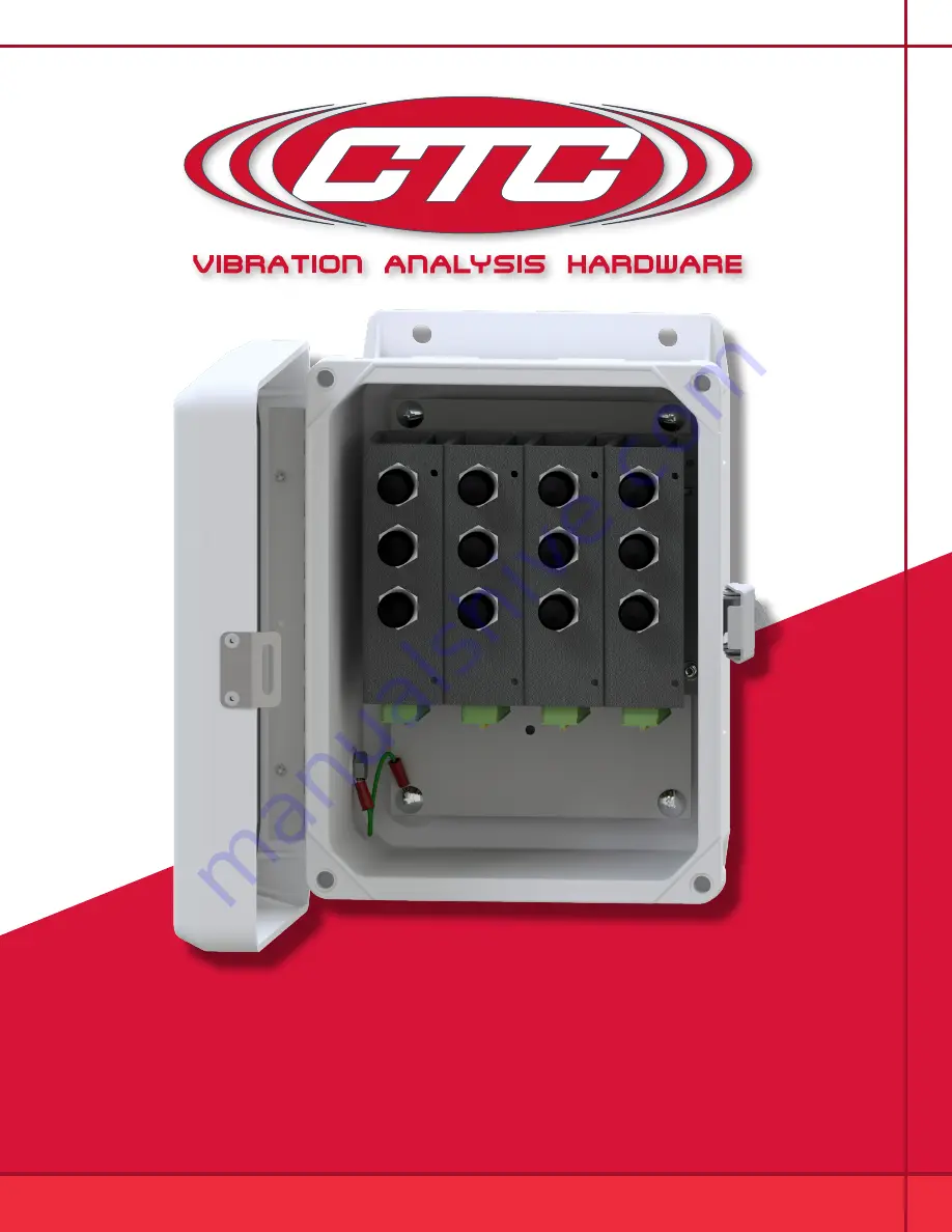
Страница 3: ...onnect terminal blocks for terminating the sensor of your choice Note If continuous output is desired CTC part number JB907 4A will accomplish that application Setup of DIP Switches In addition to the...
Страница 4: ...4 Product Dimensions Measurement Location Card BNC Output Connector Figure 1 Dimensions Figure 2 Diagram Side View Rear View...
Страница 5: ...without cable entries provided you should add your own entry prior to mounting the modular MAXX box CTC does not recommend putting holes in the top of the enclosure due to access and moisture concern...
Страница 6: ...enters from the bottom of the enclosure when mounted Note To ensure moisture will not flow into the enclosure a hole should be drilled at the lowest point in the conduit to provide drainage for any m...
Страница 7: ...grounded to earth ground A Mounting to Earth Ground When mounting MMX1000 Series Modular MAXX boxes to earth ground such as an I Beam mount the shield ground wire using a mounting bolt through one of...
Страница 8: ...d Figure 6 Ground Wire Placement Sensor Installation Installation of sensors signal input cable 1 Feed blunt end through the cable entry at the bottom of the enclosure Note it is recommended that cabl...
Страница 9: ...in wire Signal Power 4 Locate the appropriate plug identified by channel number remove the plug and install the wires using a small flathead screwdriver Push plug back into location Orientation is as...
Страница 10: ...ed on the inside front cover with a description of each measurement location Figure 10 Connecting Cables to Termination box GND GND GND GND GND GND GND GND GND Sensor Inputs Red Positive Vibration Bla...
Страница 11: ...ermination box while Person B will be located at the measurement location 2 Once positioned Person A will connect the TM1018 to the data collector output to the modular MAXX box and turn the Channel S...
Страница 12: ...2 Yellow LED Open Circuit Indicates one of the following a Cable connector is not connected to accelerometer b Cable is open circuit broken or not connected one end c Accelerometer is not functioning...
Страница 13: ...condition within 90 days of shipment Build to order products qualify for a 50 refund if returned in new condition within 90 days of shipment Custom products are quoted and built specifically to the re...