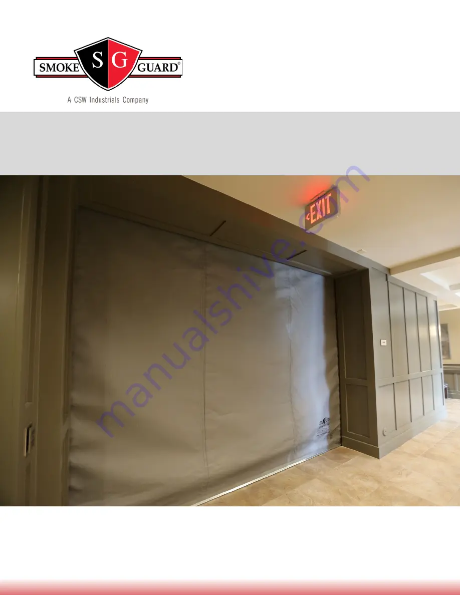
Model 2100
|
Smoke and Fire Curtain
287 N. Maple Grove. Boise, ID 83704
P. (800) 574-0330 F. (208) 639-7851
[email protected]
Installation Manual
Страница 1: ...Model 2100 Smoke and Fire Curtain 287 N Maple Grove Boise ID 83704 P 800 574 0330 F 208 639 7851 info smokeguard com Installation Manual...
Страница 2: ...9 1 Attach Up Limit Stops 17 Section 10 Cover Attachment 18 10 1 Front Cover Attachment 18 10 2 Bottom Cover Attachment 18 Section 11 Electrical Connections 19 11 1 120VAC Connections 19 11 2 Curtain...
Страница 3: ...facility it is installed in 1 1 Major Components Figure 1 The Model 2100 Fire and Smoke Curtain A M2100 Housing The Housing contains the motor Curtain and other hardware essential to the function of...
Страница 4: ...for the M2100 power system C PCA The Printed Circuit Assembly PCA controls the normal operation of the M2100 D Status LEDs and Test Switch The status LEDs indicate normal operation and errors on the...
Страница 5: ...D will blink while in jog mode WARNING Be sure the Controller is powered down before making connections Operation The curtain position can now be controlled by up down toggle switch on the transmitter...
Страница 6: ...ction Box Consult with site GC electrician to coordinate routing of conduit between Main Controller low voltage compartment and initiating device smoke detector or fire alarm Requirements conduit is r...
Страница 7: ...re assembled inside the housing Large units will have multiple housing sections that will be assembled on site The curtain assembly for large units will also take place on site Step 1 Verify the insta...
Страница 8: ...Housing WARNING It is important that the motor wires do not become entangled with the moving parts of the Curtain Assembly Zip tie the wires securely to the bracket to keep the wires away from the cur...
Страница 9: ...shaft The coupler joins the two opposite sides Figure 6 Aligning and joining the pieces of curtain barrel Step 2 Slide the longer section of tube over the coupler Step 3 Locate the welded seam on the...
Страница 10: ...seams should be used to identify the Curtain Step 7 Align the top of the Curtain with the weld seam and secure it to the Curtain Tube with the included tape Roll the Curtain around the tubing once as...
Страница 11: ...p 3 Pull the motor wire through either the hole on the top or endplate of the housing and secure in place with the included cable clamp Plug the other hole with one of the included snap in hole plugs...
Страница 12: ...ound the Clamp Rod leaving at least 1 1 2 of Curtain overlap Step 4 Bring the two halves of the Bottom Bar assembly around the Clamp Rod so that the top of the assembly halves lines up with the 1 1 2...
Страница 13: ...curtains or low profile self drilling screws NOTE If self drilling screws are used in Step 5 it will be necessary to grind off the back side to ensure there is no more than 1 8 protrusion Step 6 Using...
Страница 14: ...sewn to ensure smooth operation Step 7 Trim the excess Curtain protruding from the top of the Bottom Bar assembly Step 8 If necessary slide additonal ballast to the Bottom Bar assembly by inserting a...
Страница 15: ...it suspended in the Housing Step 3 Position the roller bracket as close as possible to the center of the Curtain so that the center most seam of the Curtain will be supported Step 4 Slots in the botto...
Страница 16: ...ING TO JAMB OR INTO POCKET Insert a drill extension with a backing appropriate anchor through the slot at the top of the Guide lower the drill to the first pre drilled hole and anchor into the wall su...
Страница 17: ...ow the Housing rather than flush with the bottom of it attach the optional Up Limit Stops to the side guide These stops will line up with the Bottom Bar assembly and stop the Curtain at the correct po...
Страница 18: ...ch the front cover s 10 2 Bottom Cover Attachment Step 1 Align the bottom cover panel s so that the angled section aligns with the front cover s angled bottom Step 2 Screw the bottom cover panel s to...
Страница 19: ...ded to be installed in accordance with the National Electric Code NFPA 80 National Alarm Code NFPA 80 and within the limits of the authority having jurisdiction 11 1 120VAC Connections Step 1 Ensure 1...
Страница 20: ...y Open contacts of the initiating device The Smoke Guard EOL Diode should be connected in parallel with these contacts order of diode wires does not matter Step 2 At the Controller low voltage compart...
Страница 21: ...nected to the lamps of each door activation switch Step 4 At the Controller low voltage compartment connect wires as follows NOTE Utilizing shorting blocks will ease making multiple connections at ter...
Страница 22: ...front panel Step 5 The Curtain will retract and record the distance travelled until the Curtain bottom stops and trips the current limit Step 6 The Curtain will then deploy and retract to verify cali...
Страница 23: ...teries that provide enough power to deploy the Curtain in the event of power loss WARNING To avoid damage to the unit verify battery connections are correct before connecting Failure to do so can resu...
Страница 24: ...l 6 No AC battery active 1 blink every 5s OFF 1 blink every 5s Low voltage power supply or main power off Running on battery Error 1 Battery health low OFF 1 blink every 5s ON Battery or Controller pr...
Страница 25: ...ID 83704 Business hours are from 7 30am 5 30pm Monday Friday Mountain Time Phone Customer service 1 800 574 0330 Customer service after hours 1 208 850 1618 Technical support 1 800 215 6138 Technical...
Страница 26: ...detector FSCS Firefighters Smoke Control Station Some building facilities incorporate this station as an aid for firefighting The M2100 has an optional interface for such a station Housing Refers to...
Страница 27: ...railing Smoke Guard Idaho based company which produces the M2100 and other fire and smoke protection systems Contact information is available in the appendix TDS Test Deploy Switch located on the Main...