XCP-Gateway
Mounting and Installation
User Guide
10
Version 01.00
User Guide
4.2
Mounting XCP-Gateway
XCP-Gateway is available in two housings: Standard (CL) and Slide Case (SCL).
See datasheet “XCP-Gateway” for further technical information.
NOTICE!
Strong magnetic fields induced e.g. by permanent magnets may impair the
proper functioning of the device.
Never attach the device to a permanent magnet.
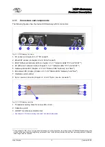
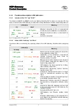
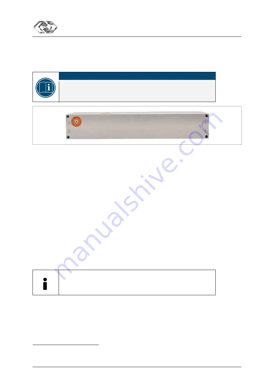
Fig. 4-2: XCP-Gateway, rear side
Preconditions
The ventilation inlet of the GORE
membrane is not blocked or obstructed in any way.
The mounting site allows for sufficient space to connect and disconnect the cables without clamping
or pinching them.
Parts/material required
4 M4 screws
2
and a matching screwdriver
further mounting material, if required (e.g. mounting bracket)
See datasheet “CSM MiniModule Accessories” for further technical information.
or
4 suitable cable ties
Mounting XCP-Gateway
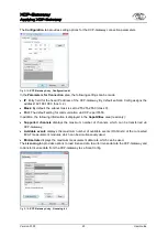
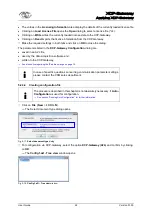
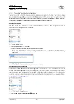
Mount the device to the selected site by screwing the four screws into the threaded mounting holes
in the rear side of the housing.
or
Fix the device using the cable ties.
CSM provides a mounting kit for standard housing devices.
Please contact the CSM sales department for further details.
Mounting modules in slide case housings
Modules in slide case housings can be stacked on each other, thus forming compact units. This is of
particular benefit when several MiniModules are to be used. Additional modules are simply stacked on
the already mounted one. Suitable adapter plates are available to attach different-sized slide case
housings to each other. The first and the last module of a module stack are fixed with mounting angles.
See datasheet “CSM MiniModule Accessories” for further technical information.
2
If a standard mounting angle from the product range of CSM MiniModule accessories is used, the screw length may not exceed
8 mm (M4 x 8 mm). In case of combination with any other mounting material, a different screw length may be required.


