

DO
GUIDE
DO
Configure the Device
Configure the Crestron
®
HD-DA-2 using DIP switches 1-7. The default setting of the DIP switches is
OFF.
NOTE:
DIP switch 8 is not used.
Refer to the following table for DIP switch functions and associated settings.
DIP Switch Settings
DIP Switch Functions
1
2
3
4
5
6
7
Audio Input Source
Selection
HDMI IN
OFF
SPDIF Source
ON
SPDIF Source,
Audio Embedding
1
AUDIO IN, SPDIF, RCA
OFF
AUDIO IN, OPTICAL
ON
Audio EDID
Control
2
Copy HDMI OUT 1
Audio EDID
OFF OFF
Copy HDMI OUT 2
Audio EDID
ON
OFF
LBR (DTS, AC3) or 2CH PCM
OFF
ON
2CH PCM Only
ON
ON
Audio/Video EDID
Control (Primary
EDID Control)
Copy HDMI 1 EDID
(Audio/Video)
3
OFF OFF OFF
Copy HDMI 2 EDID
(Audio/Video)
3
ON
OFF OFF
Copy HDMI 1 EDID
(Video Only)
4
OFF
ON
OFF
Copy HDMI 2 EDID
(Video Only)
4
ON
ON
OFF
Best Common Resolutions
(Video Only)
4
OFF OFF
ON
1. DIP switch 1 must be ON
2. May be overridden by DIP switches 5, 6, and 7
3. Overrides audio EDID set by DIP switches 3 and 4
4. DIP switches 3 and 4 control audio EDID
NOTE:
Depending on the audio/video application, a DIP switch setting may be ignored.
NOTE:
If DIP switch settings are changed after power is applied to the device, cycle power to the
device in order for the new DIP switch settings to be applied.
The following sections provide sample configurations and associated DIP switch settings for video
distribution, audio embedding, and audio extraction applications.
Video Distribution:
The HD-DA-2 can be used to distribute one HDMI
®
video source to two
devices using their best common video EDID information. In the example below, one HDMI video
source, a Blu-ray™ player, connects to the HDMI IN port of the HD-DA-2. Two displays connect to
the HDMI OUT 1 and HDMI OUT 2 ports on the HD-DA-2. The DIP switch settings shown below
configure the HD-DA-2 to both distribute video from the Blu-ray player to the two displays using
their best common video resolutions and to send 2CH PCM to both displays.
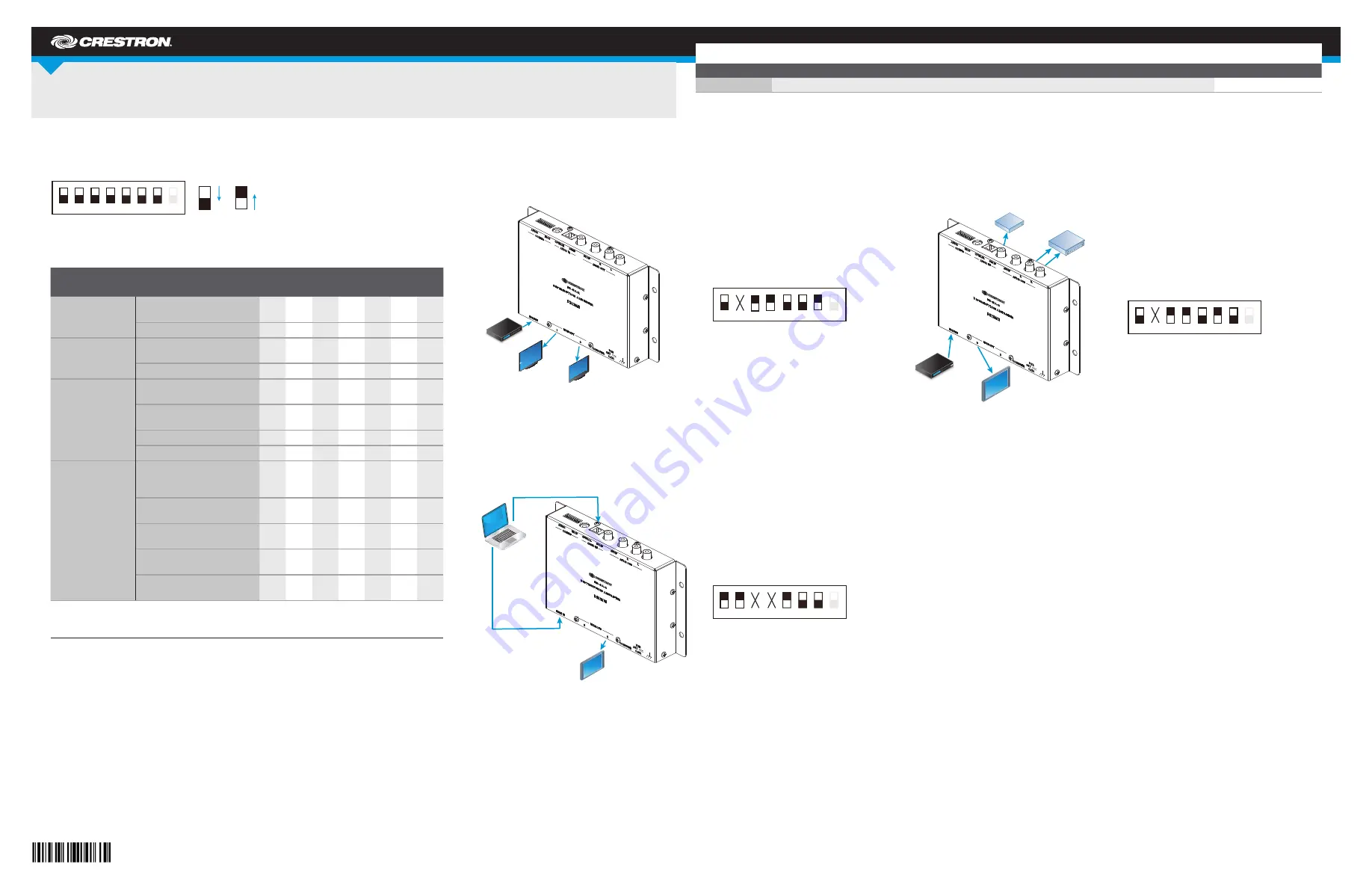
Audio Embedding:
The HD-DA-2 can be used to embed digital audio from DVI or HDMI sources
that do not transmit audio with the video (for example, video from a computer via a DVI-to-HDMI
conversion cable). Digital audio must then be sent to the HD-DA-2 separately from the video. In the
example below, the video output from a computer connects to the HDMI IN port of the HD-DA-2.
The digital audio output from the computer connects to the AUDIO IN OPTICAL port of the
HD-DA-2. A display connects to the HDMI OUT 2 port on the HD-DA-2. The DIP switch settings
shown below configure the HD-DA-2 to receive video at the HDMI IN port, to embed audio from the
OPTICAL port, and to send audio and video to the HDMI OUT 2 port.
Audio Extraction:
The HD-DA-2 can be used to extract audio from an HDMI source and feed the
audio to an AV receiver or amplifier or to both devices. In the example below, the HDMI source, a
Blu-ray player, connects to the HDMI IN port on the HD-DA-2. An AV receiver connects to the
AUDIO OUT SPDIF port, and an amplifier connects to the AUDIO OUT R and L ports. The DIP
switch settings shown below configure the HD-DA-2 to route audio from the Blu-ray player to the
AV receiver and amplifier.
DO
Set the HDCP Keys
Using the rotary switch and a small screwdriver, set the required number of HDCP keys. The rotary
switch allows up to 16 keys to be set: A-F correspond to 10-15, and 0 corresponds to 16.
NOTE:
If a rotary switch setting is changed after power is applied to the device, cycle power to
the device in order for the new rotary switch setting to be applied.
HD-DA-2
1-to-2 HDMI
®
Distribution Amplifier and Audio Converter
DO
Check the Box
QUANTITY
PRODUCT
PART NUMBER
1
Power Pack, 24 Vdc 0.75 A, 100-240 Vac
2045865
OFF
ON
1
2
3
4
5
6
7
8
Display
Display
Blu-ray
player
TM
DIP switch 2, represented by an
X
,
is ignored.
1
2
3
4
5
6
7
8
Display
DIP switches 3 and 4, each represented by
an
X
, are ignored.
1
2
3
4
5
6
7
8
Blu-ray
player
TM
Amplifier
AV
receiver
Display
1
2
3
4
5
6
7
8
DIP switch 2, represented by an
X
,
is ignored.