FlipTop Touch Screen Control System
Crestron
FT-TSC600
14
•
FlipTop Touch Screen Control System: FT-TSC600
Operations & Installation Guide – DOC. 7593A
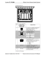
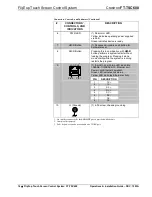
Connectors, Controls, and Indicators (Continued)
#
CONNECTORS
1
,
CONTROLS, AND
INDICATORS
DESCRIPTION
6
PWR LED
(1) Dual color LED;
Yellow indicates operating power supplied
via PoE;
Green indicates device is ready
7
HW-R Button
(1) Recessed miniature push button for
hardware reset
8
SW-R Button
Pressing this in combination with
HW-R
button performs a system restart without
loading the program. Pressing it alone
momentarily while the system is running
restarts the program
9
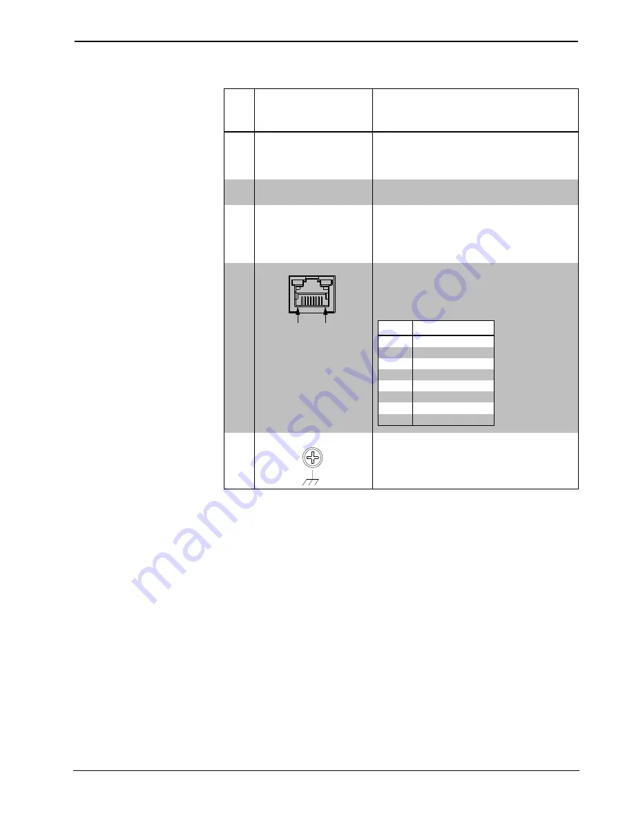
LAN PoE
3
Pin 8 Pin 1
(1) 8-pin RJ-45 with two LED indicators;
10BASE-T/100BASE-TX Ethernet port;
Power over Ethernet compliant;
Green LED indicates link status;
Yellow LED indicates Ethernet activity
PIN
DESCRIPTION
1
TX +
2
TX -
3
RX +
4
DC +
5
DC +
6
RX -
7
DC -
8
DC -
10
G (Ground)
(1) 6-32 screw, chassis ground lug
1.
An interface connector for the
AUD OUT
port is provided with the unit.
2.
Item(s) sold separately.
3.
PoE+ dc power can also be available on a TX/RX pair.
Содержание FT-TSC600 FlipTop
Страница 1: ...Crestron FT TSC600 FlipTop TouchScreenControlSystem Operations Installation Guide ...
Страница 4: ......


