background image

DualTouch™ Technology Touchpanel  

Crestron 

DTT-17


Setup 

Hardware Hookup 

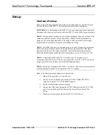
Refer to the following diagrams and complete the connections as specified. Ensure 
that the UPX-2 and the DTT-17 are both powered down before beginning.  

CAUTION: 

To avoid damage to the DTT-17 or to your video card, never connect or 

disconnect the video or power cable while the DTT-17 or the UPX-2 are powered up.


NOTE:  

The maximum continuous current from equipment under any external load 

conditions shall not exceed a current limit that is suitable for the minimum wire 
gauge used in interconnecting cables. The ratings on the connecting unit's supply 
input should be considered to prevent overloading the wiring. 

NOTE:  

The USB cable may be extended using up to four 16-foot active extensions. 

Each extension cable must contain a hub (repeater) to regenerate the USB signal 
(maximum of 64 feet). For longer extensions, Crestron has tested and approved 
IOGEAR USB Extender model GUCE50, which allows up to 150 feet over CAT5. 

NOTE:  

Using high quality cable, the VGA cable may be extended up to a 

maximum of about 10 meters (32.8 ft.) for analog VGA at 1024 x 768. If you need a 
longer run, add VGA extenders or VGA distribution amplifiers. 

NOTE:

  The native resolution of the DTT-17 is 1280 x 1024, however the resolution 

actually displayed depends on the signal the UPX-2 is sending.  

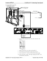
Refer to the illustrations that follow these instructions. 

1.  Slide off the protective cover on the rear. 

2.  Connect the DVI/I RGB cable, linking the UPX-2 RGB OUTPUT A 

connector to the DTT-17 DVI/I RGB connector. 

3.  Set the Analog/Digital switch to Analog. 

4.  Connect the USB cable, linking the UPX-2 USB port to the DTT-17 USB 

port. Use one of the preferred ports on the lower left rear side of the  
UPX-2. 

5.  Plug the power adaptor cable into the DTT-17 DC IN port.  


Operations Guide – DOC. 6343                  


DualTouch™ Technology Touchpanel: DTT-17 

y

    9

Содержание DualTouch DTT-17

Страница 1: ...Crestron DTT 17 DualTouch Technology Touchpanel Operations Guide ...

Страница 2: ...n by the Technical Documentation department at Crestron Electronics Inc 15 Volvo Drive Rockleigh NJ 07647 1 888 CRESTRON All brand names product names and trademarks are the property of their respective owners 2006 Crestron Electronics Inc ...

Страница 3: ...Physical Description 4 Industry Compliance 8 Setup 9 Hardware Hookup 9 Display Settings 11 Using the Pen 14 Cleaning 15 Alternative Mounting 16 Problem Solving 17 Troubleshooting 17 Further Inquiries 18 Future Updates 18 Return and Warranty Policies 19 Merchandise Returns Repair Service 19 CRESTRON Limited Warranty 19 Operations Guide DOC 6343 Contents i ...

Страница 4: ......
Страница 5: ...etween modes is automatic and instantaneous disabling the analog membrane whenever the pen is sensed allowing users to rest the palm of their hand naturally on the screen while drawing The DTT 17 includes a tabletop stand with versatile tilt adjustment Functional Summary Provides the primary user interface for the Crestron UPX 2 Universal Presentation Processor Displays high resolution RGB video f...

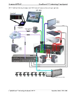
Страница 6: ...ility Management Digital Media Storage Server Computers RGB RGB Plasma Display DVD VCR DTT 15V2 UPX 2 PRO2 Webcam S Video Component Video RGB USB Streaming Video via Ethernet LAN and NetMeeting USB Control Control RoomView Control LAN Control Control Control Crestron Commercial Lighting Cresnet RGB y DualTouch Technology Touchpanel DTT 17 Operations Guide DOC 6343 2 ...

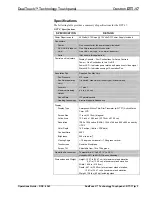
Страница 7: ...um Reading Height 0 4 in 1 02 cm Report Rate 133 points second Reading Technology Electro Magnetic Resonance Display Display Type Amorphous Silicon Thin Film Transistor a Si TFT Active Matrix Color LCD Screen Size 17 inch 43 18 cm diagonal Active Area 13 3 inch x 10 65 inch 33 79 cm x 27 03 cm Resolution 1280 x 1024 native SXGA 1024 x 768 and 800 x 600 as sent by UPX 2 Color Depth 16 2 million 18 ...

Страница 8: ...l standards Since production techniques cannot guarantee an absolutely perfect TFT display some panels may exhibit a small number of pixels that display an incorrect color This does not mean the device is defective The quality control standards are based on internationally accepted standards for LCD monitors Of the 786 432 pixels on each DTT 17 99 999 are required to function perfectly and no pixe...

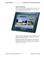
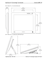
Страница 9: ...ch Technology Touchpanel Crestron DTT 17 DTT 17 Physical View Side and Front Dimensions DTT 17 Physical View Side Maximum and Minimum Height Operations Guide DOC 6343 DualTouch Technology Touchpanel DTT 17 y 5 ...

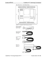
Страница 10: ...wn The DTT 17 is shipped with the following accessories One Pen with tip replacements and One Pen Stand One USB Cable Approximately 6 feet long One DVI I RGB Cable Approximately 6 feet long One Power Supply and Line Cord y DualTouch Technology Touchpanel DTT 17 Operations Guide DOC 6343 6 ...

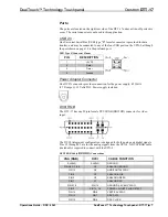
Страница 11: ...ly 45 Watts 3 75 Amps 12 Volts DC Power supply included DVI I RGB The DTT 17 has one 29 pin female DVI I RGB DB15HD connector for video input The DVI I integrated configuration is designed for both analog and digital signals Pins C1 through C5 are for the analog signals from the UPX 2 A DVI I RGB cable included is required to connect with the UPX 2 DVI I RGB Cable DB15HD Connections VGA RGB DVI I ...

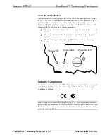
Страница 12: ...ator is blue when power is applied and a video signal is applied The status indicator is blue when the DTT 17 senses the annotation pen touchdown Power Switch Power LED Status LED Industry Compliance As of the date of manufacture the DTT 17 has been tested and found to comply with specifications for CE marking and standards per EMC and Radiocommunications Compliance Labeling NOTE This device compl...

Страница 13: ...SB signal maximum of 64 feet For longer extensions Crestron has tested and approved IOGEAR USB Extender model GUCE50 which allows up to 150 feet over CAT5 NOTE Using high quality cable the VGA cable may be extended up to a maximum of about 10 meters 32 8 ft for analog VGA at 1024 x 768 If you need a longer run add VGA extenders or VGA distribution amplifiers NOTE The native resolution of the DTT 1...

Страница 14: ...d in This Application Power Supply To AC Line Cord 6 Use the molded cable guides to secure the cables to the back of the DTT 17 7 Replace the protective cover on the back of the DTT 17 8 Connect the line cord to the power supply and an AC outlet 9 Power up the DTT 17 The power indicator should light up orange 10 Power up the UPX 2 When a video signal is applied to the DTT 17 the power indicator wi...

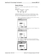
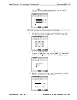
Страница 15: ...he Enter button to open and save the selected menu 1 Contrast Use the selection buttons to decrease or increase contrast Press the Enter button to save Default is 70 2 Brightness Use the buttons to decrease or increase brightness Press the Enter button to save Default is 60 3 Phase Use the buttons to manually reduce horizontal distortion lines The Reset menu is used for automatic adjustment Press ...

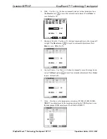
Страница 16: ...left or right The Reset menu is used for automatic adjustment Press Enter to save Default is 50 6 Vertical Center Use the buttons to manually move the image down or up The Reset option is used for automatic adjustment Press Enter to save Default is 50 7 Color Provides a color temperature selection of 9300K 6500K 5000K DIRECT no adjustment to the incoming signal and a USER option to use the indepen...

Страница 17: ...one of the available nine positions Press Enter to save Default is center position 9 Reset Use AUTO ADJUST to reset only the image parameters menus 1 through 6 Use RECALL to reset all screen options to the factory default Select the exit icon to leave this menu without making any changes 10 Backlight Use the buttons to decrease or increase the backlight brightness Press Enter to save Default is 80...

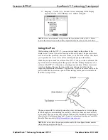
Страница 18: ...g and holding a mouse button Raising the tip above the surface of the DTT 17 is the same as releasing a mouse button If there is no eraser switch on the top of the pen the side switch is set to Eraser by default in the supporting MediaMarker Notebook application If there is an eraser switch on the pen it works like the eraser on a pencil Other settings for the pen are available via the UPX 2 setup...

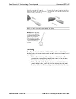
Страница 19: ... the pen and cause wear to the screen surface Regular cleaning will help to prolong the life of your equipment To clean the outer casing stand and pen use a soft cloth and a mild detergent such as dishwashing liquid diluted in water Do not use paint thinner benzene alcohol or other solvents To clean the surface of the display screen use an anti static cloth or very slightly dampened cloth Apply on...

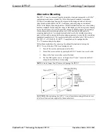
Страница 20: ... the interface mounting pads wall mount brackets and other mounting apparatus to be provided by mounting equipment manufacturers The complete standard is available on the VESA website The DTT 17 is VESA MIS D 100 75 C compliant and is equipped with a 75 x 75 mm mounting hole pattern Follow these instructions for removing the adjustable stand and attaching the DTT 17 to an alternative VESA conformi...

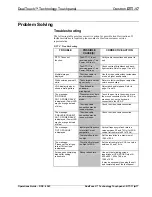
Страница 21: ...een move the mouse connected to the UPX 2 or press any key on the keyboard connected to the UPX 2 The message NO SIGNAL GO TO POWER SAVE is displayed Power LED may be orange instead of blue The video cable connection may be loose or broken Check the video cable connection The message CABLE DISCONNECT GO TO POWER SAVE is displayed Power LED may be orange instead of blue The video cable connection m...

Страница 22: ...ntains the latest firmware The DTT 17 also requires that the firmware in the UPX 2 to which it is attached be the 1GB Build firmware version 2 00 or later Please check the Crestron website for the latest version of the firmware Not every product has a firmware upgrade but as Crestron improves functions adds features and extends the capabilities of it products firmware upgrades are posted on the Cr...

Страница 23: ...scent lamps are not covered This warranty extends to products purchased directly from CRESTRON or an authorized CRESTRON dealer Purchasers should inquire of the dealer regarding the nature and extent of the dealer s warranty if any CRESTRON shall not be liable to honor the terms of this warranty if the product has been used in any application other than that for which it was intended or if it has ...

Страница 24: ...Crestron Electronics Inc Operations Guide DOC 6343 15 Volvo Drive Rockleigh NJ 07647 2012349 Tel 888 CRESTRON 01 06 Fax 201 767 7576 Specifications subject to www crestron com change without notice ...

Отзывы: