background image

122

Chapter 5—Hardware and Maintenance Repairs

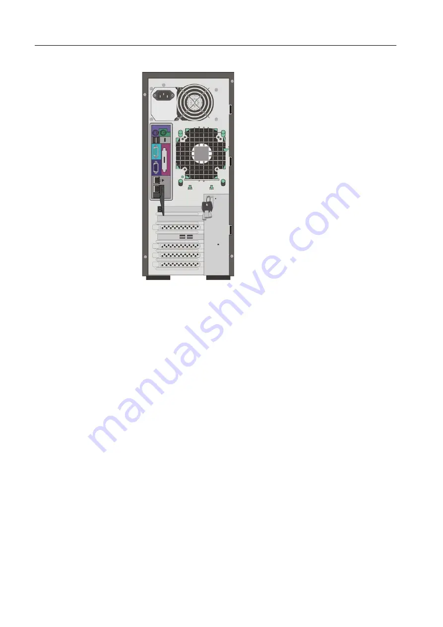
7. Gently move the power supply out of the server.

Figure 43: Removing the power supply unit 

5.9.2 Installing the Power Supply

1. Orient the power supply and place it into the server. 

2. Insert the power supply into the opening at the rear of the chassis.

3. Align the holes in the power supply with the holes in the chassis.

4. Insert the four power-supply screws, and tighten them.

5. Reconnect the internal cables from the power supply to the system board and 

drives.

6. Return the side cover. Se

Placing the Side Cover

 on page 95.

7. Reconnect all external cables and AC power cords, and turn on the server.

Содержание Color Controller C-80

Страница 1: ...Technical Manual English Color Controller C 80 Powered by Creo Color Server Technology for Pro C900 734 00932A EN Version 1 0...

Страница 2: ......

Страница 3: ...n advised of the possibility of such damages resulting from i the use or the inability to use the product or software ii the cost of procurement of substitute goods and services resulting from any pro...

Страница 4: ...didate list according to article 59 1 of Regulation EC No 1907 2006 REACH CE Marking Traceability Information For EU Countries Only Manufacturer Kodak IL LTD P O Box 10193 Petach Tikva 49002 Israel Au...

Страница 5: ...de seguran a xii Seguran a geral xii Troca de bateria xii Eletricidade est tica xii 1 Product Overview 1 1 1 Introduction 2 1 1 1 Color Controller C 80 Components 2 1 1 2 Functionality and Features 3...

Страница 6: ...ls Overview 48 4 1 2 Using the Configuring Tools 50 4 2 General Diagnostic Tools 58 4 2 1 PC Health Monitoring 58 4 2 2 POST Power On Self Test 59 4 3 Color Controller C 80 Hardware Diagnostics Softwa...

Страница 7: ...stalling the DVD RW Drive 119 5 8 Replacing a Hard Disk 119 5 8 1 Removing a Hard Disk 120 5 8 2 Installing a Hard Disk 120 5 9 Replacing the Power Supply 121 5 9 1 Removing the Power Supply 121 5 9 2...

Страница 8: ...vi Color Controller C 80 1 0 Technical Manual...

Страница 9: ...ormation Multi Language Safety Precautions vi Sicherheitsma nahmen vii Medidas Preventivas de Seguridad viii Mesures de s curit ix Precauzioni di Sicurezza x Veiligheidsmaatregelen xi Precau es de seg...

Страница 10: ...me circuits energized For complete disconnection from the supply the main power cable must also be disconnected from the power source Battery Replacement Only qualified service personnel should replac...

Страница 11: ...ert Um eine vollst ndige Trennung von der Stromversorgung zu erreichen muss der Hauptlastschalter von der Stromquelle getrennt sein Batterieaustausch Die Batterie sollte nur von qualifiziertem Kundend...

Страница 12: ...n completa del suministro de energ a el cable de alimentaci n principal se debe desconectar de la fuente de alimentaci n Sustituci n de la bater a S lo un ingeniero de mantenimiento y reparaciones deb...

Страница 13: ...alimentation en courant le c ble d alimentation principale doit aussi tre d connect du bloc d alimentation Remplacement de la batterie Le remplacement de la batterie est une op ration r serv e au per...

Страница 14: ...una sconnessione completa dalle fonti di alimentazione il cavo di alimentazione principale deve essere staccato dal connettore di alimentazione Sostituzione della Batteria La batteria dovrebbe essere...

Страница 15: ...tscircuits geactiveerd blijven Om de stroomtoevoer volledig af te sluiten moet de electriciteitskabel uit het stopkontact zijn De batterij vervangen De batterij mag alleen door bevoegd servicepersonee...

Страница 16: ...dos Para uma desconex o completa da fonte de alimenta o o cabo de alimenta o principal tamb m deve ser desconectado da fonte de alimenta o Troca de bateria A bateria deve ser substitu da somente por u...

Страница 17: ...1 Product Overview Introduction 2 Product Configuration 4...

Страница 18: ...tions The Color Controller C 80 processes files in PDL for example PostScript PDF and VDP formats converting them into a suitable ready to print format for direct high quality printing The Color Contr...

Страница 19: ...Post RIP imposition Job management On screen preview and editing Print jobs at machine rated speed RIP Adobe Postscript Level 3 and Extreme certified technologies Ready to print job format for immedia...

Страница 20: ...disk 250GB hard disk Windows XP Professional loaded on C Default Windows based computer and Macintosh shared folder including various utilities and PPD on D Default path for APR high resolution files...

Страница 21: ...D Gigabit ethernet connection Enables high speed connection to the network 1 1 5 Disk Configuration The following table outlines the Color Controller C 80 disk configuration Disk 0 C Windows XP Profes...

Страница 22: ...6 Chapter 1 Product Overview...

Страница 23: ...2 First Time Setup and Configuration Connecting the Color Controller C 80 8 Configuration Wizard First time Software Setup 11 Configuring McAfee VirusScan 29...

Страница 24: ...he printer display panel press Clear Modes 2 Type 107 and press C Clear until the SP mode appears 3 Touch System Sp 4 Use the buttons on the touch screen to navigate to the SP5193 001 setting External...

Страница 25: ...on the printer Figure 3 Printer and Color Controller C 80 connection Note To prevent the risk of crosstalk make sure the printer interface cable does not touch the system s power cables The Color Cont...

Страница 26: ...s before pressing the power control button on the Color Controller C 80 see Figure 4 on page 10 The ON OFF LED on the front panel illuminates a steady green After the system startup is complete the Wi...

Страница 27: ...he Color Controller C 80 for the first time the Configuration Wizard appears The first time software setup is performed using the Configuration Wizard 2 2 1 Choosing the Configuration Type Verify that...

Страница 28: ...e of the Color Controller C 80 is created automatically during the factory installation To change the computer name check with your system administrator 1 In the Server name area verify that the corre...

Страница 29: ...lick OK Setting the Date and Time 1 In the Date Time tab verify that the date and time are set correctly If they are correct proceed to Configuring the Network Setup on page 14 2 If you want to change...

Страница 30: ...twork Setup Configuring TCP IP Addresses 1 In the TCP IP area verify that the IP address is correct If it is correct proceed to Configuring the IPv6 Address on page 15 If the IP address is not correct...

Страница 31: ...applicable 4 Click OK 5 In the Local Area Connection Properties dialog box click OK Configuring the IPv6 Address 1 In the IPv6 Address area verify that the address is correct 2 If it is correct proce...

Страница 32: ...r Configuring the AppleTalk Zone This option enables you to change the AppleTalk network zone in which your Color Controller C 80 appears 1 In the Apple Talk setup area verify that the displayed Apple...

Страница 33: ...ed zone and click OK 3 In the Local Area Connection Properties dialog box click OK 2 2 4 Configuring the Remote Tools Setup The WebViewer provides server information and enables you to view the status...

Страница 34: ...hours 4 Click Remote Connections Viewer to view the remote connections 2 2 5 Configuring Security Settings Using the Default Password Settings Note The factory default password for Administrator and O...

Страница 35: ...k Wipe Setting The Disk Wipe utility enables you to work in a more secure environment by permanently removing data left by files that you have deleted The utility eliminates the contents of your delet...

Страница 36: ...e of the following options If the disk space is correct proceed to the next screen in the wizard If you need to change the amount of free disk space enter the correct minimum disk space that you requi...

Страница 37: ...d in the path box If the backup is made to external media the displayed path is the default C ColorControllerC 80 General Configuration 2 2 8 Setting the Calibration Reminder Set the calibration remin...

Страница 38: ...Parameters You configure the measurement unit and language in the Localization window 1 In the Units list select the required default measurement unit 2 In the Language list select the required inter...

Страница 39: ...lect one of the following After 30 days After 12 hours Then enter the desired number of days or hours Note Change the number of days or hours depending on your site requirements 2 In the Held jobs are...

Страница 40: ...1 In the PostScript preview area specify the desired action when you close the Adobe Acrobat preview window Save file as PDF Return to the original PostScript file 2 In the VDP jobs preview area sele...

Страница 41: ...ing jobs that have similar attributes and enable the printer to pause in between printing jobs Held Jobs Policy In the Held jobs policy area do one of the following Select Bypass held jobs to bypass h...

Страница 42: ...erent than 90 days 2 In the Message viewer log setup area enter the number of days after which you can overwrite messages if different than 90 days 2 2 14 Configuring JDF Output and JMF Signals The Co...

Страница 43: ...rea select the Send JMF signals check box to receive JMF signals about the job s status 4 In the HTTP URL box type HTTP URL This enables you to submit JMF signals with the job status each time that th...

Страница 44: ...e when printing via LPR Uses the job s given file name Selecting this option ensures that the job appears in the Color Controller C 80 with the name last given by the user Cached global VDP elements S...

Страница 45: ...the following configuration procedures Once a year the site manager must obtain the latest version of the antivirus software and installation procedure The site manager must also regularly download th...

Страница 46: ...First Time Setup and Configuration 4 In the What not to scan area click Exclusions 5 Click Add 6 Click Browse 7 In the Browse for Folder dialog box locate the D Output folder and click OK The D Output...

Страница 47: ...ct the Also exclude subfolders check box and click OK 9 In the Set Exclusions dialog box click OK and then click OK again 2 3 2 Configuring the On Access Scan Settings 1 Return to the VirusScan Consol...

Страница 48: ...2 Chapter 2 First Time Setup and Configuration 2 In the Task area right click On Access Scanner and select Properties 3 On the left of the window click the All Processes icon 4 Select the Detection ta...

Страница 49: ...ons 6 In the Set Exclusions dialog box click Add 7 Click Browse 8 In the Browse for Folder dialog box locate the D Output folder and click OK 9 Select the Also exclude subfolders check box and click O...

Страница 50: ...orage area Note If the job does not print or is waiting in the Print Queue make sure that the default virtual printer parameters are set to the current finishing device Job Parameters Finishing To imp...

Страница 51: ...lor problems On the printer control panel enter the SP mode and then execute the process control with SP3 820 002 For density difference problems Perform color calibration on the Color Controller C 80...

Страница 52: ...36 Chapter 2 First Time Setup and Configuration...

Страница 53: ...3 Reinstalling the Color Controller C 80 Software When To Reinstall 38 Installing the Operating System and Software 39 Backing Up the System Partition 42 Restoring the System Partition 44...

Страница 54: ...ically replacing the system disk When upgrading the system disk Preservation Installation System Partition Overwrite This procedure requires two discs DVD 1 and DVD 2 It installs the Color Controller...

Страница 55: ...ng information is available for the Color Controller C 80 Computer name TCP IP information Gateway WINS address and DNS information if DHCP is not active on site AppleTalk zone information IPX informa...

Страница 56: ...the option you want to perform Press 1 to perform a complete installation Press 2 to perform preservation installation The confirmation message Are you sure appears 4 Press y Yes to confirm your selec...

Страница 57: ...window opens click Yes to continue the Color Controller C 80 installation 13 When the installation is complete a Click Finish to restart the computer b Remove DVD 2 from the DVD RW drive When the appl...

Страница 58: ...3 to use the System Backup Tool 6 Type Y to confirm your selection The System Backup Restore Tool menu appears Attention Before performing the backup and restore procedures make sure that your comput...

Страница 59: ...DVD for the backup a Press Y to continue The following message appears b To continue press Y The following message appears c Follow the instructions in the message Norton Ghost copies the files on pa...

Страница 60: ...Restart OK After the system restarts the Color Controller C 80 Startup Menu appears The following options are available 4 Press 3 to use the System Backup Restore Tool 5 Press Y to confirm your select...

Страница 61: ...E to restart 7 To restore partitions C and D press 4 This option restores partitions C and D from a backup media a Press Y to continue b Press Y to continue c Follow the instructions in the message d...

Страница 62: ...Software e When a confirmation message appears notifying you that the restore process was successfully completed remove the DVD from the DVD RW drive and press any key to continue The computer restart...

Страница 63: ...4 Diagnostics and Troubleshooting Platform Diagnostics and Configuring the Server 48 General Diagnostic Tools 58 Color Controller C 80 Hardware Diagnostics Software 60 Troubleshooting 67...

Страница 64: ...hange assignments for devices and I O ports Set the date and time Set the startup characteristics of the server and the order of startup devices Set and change settings for advanced hardware features...

Страница 65: ...t the problem persists try a different cable Check the LAN activity light on the rear of the Color Controller C 80 The LAN activity light illuminates when the Ethernet controller sends or receives dat...

Страница 66: ...uring the BIOS Starting the Phoenix cME FirstBIOS Pro Setup Utility 1 Quit the color server software 2 Restart the Color Controller C 80 and immediately press DELETE The Phoenix cME FirstBIOS Pro Setu...

Страница 67: ...24 hour format hour minute second System Date Sets the system date The system date is in the format month day year Hard Disk Pre Delay Adds a delay before the HDD is accessed by the BIOS for the firs...

Страница 68: ...ure is for debugging only C1 Enhanced Mode If enabled this feature lowers the CPU voltage and frequency to prevent overheating Intel Virtualization Technology If enabled this feature utilizes enhanced...

Страница 69: ...nu Exit Saving Changes This option allows you to save any changes that you made and to exit the BIOS setup utility Setup Utility Exit Discarding Changes This option allows you to exit the BIOS setup u...

Страница 70: ...ge the System Date and verify that the rest of the settings are the same as the settings in the following window a Press ENTER to save any changes 3 Using the arrow keys select the Advanced menu 4 Usi...

Страница 71: ...return to the Advanced menu 7 Using the arrow keys select Advanced Processor Options and press ENTER 8 Verify that the settings are the same as the settings in the following window 9 Press ESC to ret...

Страница 72: ...he following window 12 Press ESC to return to the Advanced menu 13 Using the arrow keys select Hardware Monitor and press ENTER 14 Verify that the settings are the same as the settings shown in the wi...

Страница 73: ...pears in the Excluded from boot order list do the following a Using the arrow keys select the device that you want to appear in the Boot priority order list b On your keyboard press the X key to add t...

Страница 74: ...r that enables the operating system to address the controller is automatically installed from DVD 1 Fast Install SLP 4 2 General Diagnostic Tools The following tools are available to help you identify...

Страница 75: ...eeds a certain threshold This works to protect the CPU from being damaged by overheating Hardware BIOS Virus Protection The system BIOS is protected by hardware so that no virus can infect the BIOS ar...

Страница 76: ...000 XP and enables local diagnostic testing of Color Controller C 80 products with user level support Code Beep POST Routine Description Recovery Action 16h 1 2 2 3 BIOS ROM checksum Try saving the BI...

Страница 77: ...st of all units by selecting the DFE option Results appear as PASS FAIL 4 3 1 Activating the Diagnostics Software Quitting the Color Controller C 80 Software 1 In the Color Controller C 80 workspace c...

Страница 78: ...ew Control Level and Help The next section under the Main Menu bar contains shortcut buttons for performing the main JOIND operations The third section is a monitoring area in which the progress of th...

Страница 79: ...be run Import Log File Imports the JOIND current log file in which the Pass Fail data is stored from the control station or process print station to the client Exit To exit the application Test Log Fi...

Страница 80: ...d by any test whichever comes first When Loop On is selected the test session repeats until the loop termination condition is reached or once a failure is detected whichever comes first User The defau...

Страница 81: ...ffer for all tests run or a Quick Batch The contents of this buffer are recorded in an HTML file which appears through the HTML browser Enables quick access to the Error Buffer of a selected test The...

Страница 82: ...Activating the Diagnostics Software on page 61 2 Select the components for testing from the diagnostics tree or select DFE to test the entire tree or select Load Quick Batch from the File Menu See Fil...

Страница 83: ...cable faults Temperature and general power checkouts Handling error messages Collecting data log files Formatting image disks Disk striping Symptom Recovery Action FusionRA board fails the test 1 Veri...

Страница 84: ...short circuits between the system board and the chassis The memory DIMMs are correctly seated Then 1 Turn the power on and off to test the system 2 The battery on your system board may be old Verify t...

Страница 85: ...row keys to select the Boot menu 4 Verify the boot order is the same as shown in step 16 on page 57 5 Reload the operating system see page 39 6 Replace the system disk Symptom Recovery Action The Fusi...

Страница 86: ...ly set 6 If the memory tests fail replace the failing DIMM Symptom Recovery Action The Color Controller C 80 monitor is blank Verify that 1 The power cord is plugged into the Color Controller C 80 and...

Страница 87: ...No Operating System on page 69 The DVD RW drive is not identified 1 Restart the server and press DEL to enter the BIOS setup utility Setup Utility See Using the Phoenix cME FirstBIOS Pro Setup Utilit...

Страница 88: ...troller C 80 port 3 Start the server 4 Wait until the Color Controller C 80 splash screen disappears 5 Start your printer If printing fails refer to the next symptom Before you print the printer anima...

Страница 89: ...on from the minimal configuration replace FRUs of minimal configuration one at a time until the problem is isolated 4 4 9 Temperature Checkout Accurate cooling of the system is important for proper o...

Страница 90: ...is replaced within 48 hours 4 4 10 Error Messages There are four types of error messages System Hardware Software Connection Each error message indicates a problem and sometimes also a recovery action...

Страница 91: ...ted correctly and restart the system 2 Run the diagnostics test 3 If the error message still appears replace the board Message Recovery Action Failed to spool the file during job submission Check the...

Страница 92: ...oceed to step 3 2 If you want to save the cab file to another location click Browse select the new location click Save and then OK 3 Restart the Color Controller C 80 software 4 Recreate the problem y...

Страница 93: ...recognizes foreign disks See Striping Foreign Disks on page 78 An image disk either has been replaced with a new disk and the operating system identifies it as an unknown disk See Striping Unknown Dis...

Страница 94: ...ng Disk on page 82 3 After completing disk striping the following message appears 4 Click OK Striping Foreign Disks Perform the following procedure to remind the operating system that a striped volume...

Страница 95: ...p 3 of 3 disks selected check box is selected and click OK 4 Click OK The Dynamic disks are striped as shown in the following window Note Foreign disks are any hard disks that were recognized as dynam...

Страница 96: ...following procedures describe how to initialize unknown disks to basic disks and to convert basic disks to dynamic disks Perform the following procedures if you have replaced an image disk To initial...

Страница 97: ...nverting the Disks to Dynamic Disks 1 In the Computer Management window right click in the disk area that you want to convert and select Convert to Dynamic Disk 2 Select the disks to convert to dynami...

Страница 98: ...milar to the following window 4 Proceed to Creating a Striped Volume Removing a Missing Disk Perform the following procedure when you have replaced a faulty disk and the new disk is intermittenly unav...

Страница 99: ...Volume Creating a Striped Volume After you have replaced a disk or low level formatted one or more disks you need to create a striped volume 1 In the Computer Management window right click the white...

Страница 100: ...4 Diagnostics and Troubleshooting 4 In the Available list select each disk that you want to include in the new volume and click Add 5 Click Next 6 Select Do not assign a drive letter or drive path and...

Страница 101: ...lect Do not format this volume and click Next 8 Click Finish 9 Confirm that the disks are striped Confirming the Disk Striping After you complete the New Volume Wizard the Computer Management window a...

Страница 102: ...when suggested as a recovery action 1 Close all software programs and wait for them to shut down completely 2 From the Windows Start menu select Color Controller C 80 Color Controller C 80 Tools Form...

Страница 103: ...87 5 Click Yes 6 Click OK 7 To enable the changes to take effect restart your computer...

Страница 104: ...88 Chapter 4 Diagnostics and Troubleshooting...

Страница 105: ...Parts List 91 Before You Begin 93 Removing and Placing the Side Cover and Front Panel 94 Working with Boards Adapters 98 Working With the System Board 103 Replacing the DVD RW Drive 118 Replacing a Ha...

Страница 106: ...the following diagram to locate a specific part for replacement In the Spare Parts List on page 91 each number in the Item number column corresponds to a spare part not all the parts in the spare par...

Страница 107: ...h DFE Net Cable Protector 252 21226A Creo 1 10 FusionRA LF Board 503 00561B Creo 1 11 Universal Stand Type II 518 01588A Creo 1 12 CPU Kit Q9400 Quad Core2 2 66GHZ 1333MHZ 518 03787A 1 13 Kit Color Co...

Страница 108: ...3 2 26 SATA Cable Straight Right Angle UP 609 00564 5 27 P S ATX 350W 6 SATA Connectors 609 00568 Third party 1 28 Color Controller C 80 Media Software Kit V1 0 634 00634A Creo 1 Color Controller C 80...

Страница 109: ...blade screwdriver available 5 3 1 System Reliability Considerations To help ensure proper cooling and system reliability verify that The side cover is in place during normal operations There is space...

Страница 110: ...Front Panel This section describes the procedures used to remove and place the Color Controller C 80 cover and front panel 5 4 1 Removing the Side Cover 1 Turn off the Color Controller C 80 and all pe...

Страница 111: ...s in the side cover with the matching tabs in the chassis Insert the side cover into the slots 5 Slide the side cover toward the front of the server 6 Tighten the two screws that secure the side cover...

Страница 112: ...e front of the chassis and move the edge of the front panel slightly away from the chassis See step 4 in Figure 10 and Figure 11 on page 97 5 Using a flat screwdriver gently pry the four concealed tab...

Страница 113: ...roller C 80 on its side insert the concealed tabs along the bottom edge of the front panel into the matching slots in the chassis 2 Push the top of the front panel toward the server until the two prot...

Страница 114: ...nnectivity 5 5 1 Visual Inspection Whenever you replace any component in the unit 1 Check that all boards are retained properly in their slots 2 Check that the cables are routed properly 3 Check the e...

Страница 115: ...emoving and Placing the Side Cover and Front Panel on page 94 4 Using a cross head screwdriver remove the hexagonal screws that hold the board at the right and the left of the chassis 5 Grip the front...

Страница 116: ...e expansion slot and is locked in position 3 If you have other options to remove or replace do so now 4 Insert the hexagonal screw that holds the board at the rear of the chassis and tighten it 5 Inse...

Страница 117: ...6 on page 102 Removing a DIMM 1 Press down on the two DIMM release tabs so that they rotate outward releasing the memory from its seat 2 Gently pull the DIMM up and out of the server Note Removing or...

Страница 118: ...one at a time on the edges of the DIMM Ensure that you press the DIMM vertically into the tab See Figure 16 Figure 16 Installing a DIMM 5 Verify that the release tabs are in the closed position If a g...

Страница 119: ...removing and installing the system board 5 6 1 System Board Internal Cable Connectors The following illustration identifies system board connectors for internal cables Figure 17 System board internal...

Страница 120: ...eplacing the Central Processing Unit CPU on page 109 7 Remove the eight system board screws 8 Release the system board from the RFI clips by sliding the system board away from the rear of the server 9...

Страница 121: ...y unpainted metal surface on the server then remove the system board from the package and place it on the worktable 4 Turn over the system board 5 Attach the metal bracket to the system board Attentio...

Страница 122: ...he bracket so that it is face down and align it with the diagram on the system board Figure 20 Diagram of metal bracket b When the bracket is properly aligned the four ends should fit into place over...

Страница 123: ...sis 11 Insert the eight screws into the holes Do not tighten the screws until all the screws are inserted 12 Return the rear fan See Installing the Rear Fan on page 124 13 Return the memory modules Se...

Страница 124: ...te To assist you in reconnecting the cables to the system board see the following table and Figure 17 on page 103 Cable System Board Connector Power supply JPW1 JPW2 USB USB 3 4 J46 USB 2 3 J44 Serial...

Страница 125: ...t all external cables and power cords 3 Remove the side cover See Removing the Side Cover on page 94 4 Remove the FusionRA board See Removing the FusionRA Board on page 99 5 Remove the rear fan See Re...

Страница 126: ...ink assembly up and out of the server Removing the Microprocessor 1 Unlock the microprocessor socket a Using your thumb press the socket lever to release the metal frame from its locking position CPU...

Страница 127: ...tal plate 2 Using your thumb and index finger carefully grasp the microprocessor by its north and south center edges and lift it up and out of the server Figure 28 Removing the microprocessor 3 Store...

Страница 128: ...Unlock the microprocessor socket a Press the socket lever down to release the load plate from its locking position The load plate covers the microprocessor socket Figure 29 Microprocessor socket leve...

Страница 129: ...ket a Make sure that Pin 1 of the microprocessor socket is located at the left bottom of the microprocessor housing 4 Insert the microprocessor into the microprocessor socket Figure 32 Aligning the mi...

Страница 130: ...four corners of the microprocessor to make sure that it is properly installed Figure 33 Checking that the microprocessor is properly installed 5 Using your thumb gently push the socket lever down and...

Страница 131: ...s in the CPU fan and heat sink assembly with their corresponding holes on the system board Insert the four spring screws and tighten Thermal grease Important Make sure to insert and secure the spring...

Страница 132: ...mber CR2032 To avoid possible danger read and comply with the following safety statement The battery is located on the system board below slot 5 See Figure 13 on page 99 Removing the Battery 1 Follow...

Страница 133: ...he battery Installing the Battery 1 Tilt the battery so that you can insert it into the socket on the side opposite the battery clip 2 Press the battery down into the socket until it clicks into place...

Страница 134: ...ect all power cords and external cables 3 Remove the side cover See Removing and Placing the Side Cover and Front Panel on page 94 4 Disconnect the cables connected to the DVD RW 5 Press the retaining...

Страница 135: ...ack up the system configuration Preferences window See Color Controller C 80 Powered by Creo Color Server Technology for Pro C900 User Guide 731 01699A EN 2 Replace the disk page 119 3 Reinstall DVD 1...

Страница 136: ...ver Figure 41 Removing a hard disk drive 6 Identify which hard disk you want to remove 7 Loosen the two screws on either side of the disk drive and pull the disk drive out of the chassis 5 8 2 Install...

Страница 137: ...ds and turn on the server 5 9 Replacing the Power Supply Perform the following procedures to replace the power supply 5 9 1 Removing the Power Supply 1 Review Safety Information Multi Language on page...

Страница 138: ...erver 2 Insert the power supply into the opening at the rear of the chassis 3 Align the holes in the power supply with the holes in the chassis 4 Insert the four power supply screws and tighten them 5...

Страница 139: ...ff the Color Controller C 80 and peripheral devices Disconnect all AC power cords and external cables 3 Remove the side cover See Removing the Side Cover on page 94 4 Disconnect the fan cable from the...

Страница 140: ...g the other four tabs with their respective slots 4 Press the rear fan bracket against the rear of the server until all the tabs are in their slots and then move the rear fan bracket downward until it...

Страница 141: ...ce the fan bracket on the new PCI fan 2 Place the PCI fan in position in the front of the server 3 Guide the two locking tabs through the top of the slots 4 Press the fan bracket against the rear of t...

Страница 142: ...126 Chapter 5 Hardware and Maintenance Repairs...

Страница 143: ...A Specifications and Standards Environmental Requirements 128 Installation Steps 128 Specifications 128 Operating Environment 129 Standards 130 Reliability and Maintenance 131...

Страница 144: ...time approximately 15 minutes A 3 Specifications A 3 1 Dimensions and Weight Color Controller C 80 D x W x H cm D x W x H in Weight Unpacked 58 8 20 44 23 1 7 9 17 3 16 8 kg 37 lb Packed 63 78 5 46 2...

Страница 145: ...without wheels Keyboard D x W x H cm D x W x H in Weight Unpacked 44 17 3 17 7 2 1 kg 2 2 lb Packed 55 21 4 21 8 2 1 kg 2 2 lb Stand Contents and Carton Optional D x W x H cm D x W x H in Weight Unpa...

Страница 146: ...sity of 1m2 s3 in frequency range of 10 200 Hz and acceleration spectral density of 0 3 m2 sec3 in frequency range of 200 2000 Hz Free fall Shipping 0 25 m Static load Shipping 10 Kpa Stacking Shippin...

Страница 147: ...ia and New Zealand CISPR 22 2006 class B Europe EMC Directive 89 336 EEC European EMC standards Radiated Emissions EN55022 2006 A1 2007 Class B Harmonics EN61000 3 2 2006 Flicker EN61000 3 3 1995 A1 2...

Страница 148: ...B X7SBL LN2 154 641 CMPTR MEM MODULE 1GB DDR2 ECC 800MHZ 4 887 586 UP Q9400 QUAD CORE2 2 66GHZ 6M 1333MHZ 90 909 CMPTR REAR FAN 120X120X25 98CFM 12VDC 27 998 FAN AXIAL 12V DC 92 92 25 42 CFM TACH 34 9...

Страница 149: ......

Страница 150: ......

Отзывы: