background image

8

Center Speaker Stand 
Installation

Unlike the Desktop Stand (for 
Satellites), the stands for the Center 
Speaker are of the screw-in type.
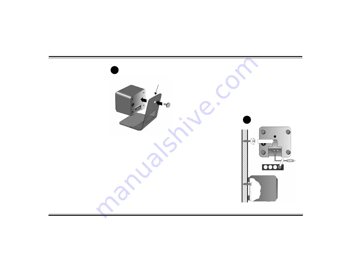
1. Align the Attachment Arm to 

the Center Speaker (see 

Diagram B)

.

2. Use the screw provided to 

connect the Attachment Arm to 
the Center Speaker.

Screw Mounting

Mounting the rear satellites on side 
walls will give you superior surround 
effects. 

For a secure installation, mount the 

rear satellites only on walls that are 
structurally sound.
1. Place the following near you: rear 

satellites, screws, plastic anchors 
and rubber pads (supplied). You 
will also need a drill and hammer.

2. Mark the wall where each rear 

satellite screw will be. Position 
the speakers behind you and 
slightly above ear level.

3. Drill a hole about 2 cm (1 inch) 

deep into each wall. Tap a plastic 
anchor into the hole until it is 
flush with the wall (see 

Diagram 

C

).

4. Screw a M5 x 25 mm screw into 

each anchor, leaving about 
0.5 cm (¼ inch) of the screw 
protruding.

5. Apply four rubber pads on the 

corners at the back of each rear 

satellite. The rubber pads will 
cushion the satellites from any 
vibration and help keep them in 
position.

6. Slip the keyhole of each rear 

satellite onto a protruding screw 
to complete the installation.

B

Attachment Arm

Mounting Speakers

C

Содержание DTT 3500 Digital

Страница 1: ...DTT 3500 Digital User Guide On line Version ...

Страница 2: ...ity to operate the device Notice for Canada This apparatus complies with the Class B limits for radio interference as specified in the Canadian Department of Communications Radio Interference Regulations Cet appareil est conforme aux normes de CLASSE B d interference radio tel que spe cifie par le Ministère Canadien des Communications dans les règlements d interfèrence radio Declaration of Conform...

Страница 3: ...ing one blade wider than the other This plug will fit into the power outlet only one way This is a safety feature If you are unable to insert the plug fully into the outlet try reversing the plug If the plug should still fail to fit contact your electrician to replace your obsolete outlet Do not defeat the safety purpose of the polarized plug POWER CORD PROTECTION Power supply cords should be rout...

Страница 4: ...am 4 Signal Source Connections 5 Signal Source Connection Diagram 6 Speaker Cable and Stand Installation 7 Mounting Speakers 8 Speaker Placement 9 Decoder Amplifier Placement 12 Decoder Amplifier Functions 13 Surround Reference 15 Multiple Connections 17 Applications Guide 18 Playback Levels 21 Specifications 21 EAX 21 1 Year Limited Warranty 22 Technical Support 22 ...

Страница 5: ... In some of today s best CD based action games DTT3500 Digital can decode the Dolby Digital cut scenes while offering enveloping positional multi channel audio It s ready for the new era of DVD based games Also included is Creative Multi Speaker Surround CMSS which lets you hear all of your favorite stereo program material with a new and exciting three dimensional quality DTT3500 Digital comes equ...

Страница 6: ...ries or Creative Labs Sound Blaster PCI series Sound Blaster Live owners should utilize the exclusive Digital DIN connection to hear the clearest digital audio available 3 Conventional 2 channel sound cards such as Sound Blaster 16 or the Sound Blaster AWE series can also be used with the DTT3500 Digital 4 Game consoles like the PlayStation 2TM using the Optical or Analog Line In connections Inven...

Страница 7: ...Digital read Substituting a powered subwoofer on page 11 7 Connect the Power Adapter to the Decoder Amplifier 8 Turn on the power Use the TEST function on the Remote Control to position and balance the speakers 9 You may wish to experiment with speaker placement briefly before concealing the connecting cables and making the installation more permanent 10 The unit is ready for you to enjoy Speaker ...

Страница 8: ...4 Front Left Satellite Rear Left Satellite Rear Right Satellite Front Right Satellite Power Adapter Center Speaker Subwoofer Speaker System Connection Diagram ...

Страница 9: ...with optical output Connect the optical output of these devices e g CD or MD players to the OPTICAL input with the Optical Cable For Sound Blaster Live sound cards with Digital Out output Connect the sound card s Digital Out output to the Digital DIN input with the Minijack to DIN Cable and the SPDIF DIN Cable For DIN Bracket bundled with Live Drive IR Connect its Digital DIN output to the DIGITAL...

Страница 10: ...tput Bundled with Live Drive IR REAR OUT LINE OUT DIGITAL OUT OPTICAL OUTPUT DIGITAL OUT Stereo to Dual RCA Cable SPDIF Cable RCA to RCA Optical Cable Tandem Audio Cable SPDIF DIN Cable 2 Ch Sound Card Output Eg Sound Blaster AWE64 LINE OUT Lime Green Black Lime Green Lime Green Black Digital Output Sound Blaster 5 1 Sound Card Minijack to DIN Cable White Red COAXIAL OUTPUT DIGITAL OUT OR OR ...

Страница 11: ...at this process using another 3 meter Speaker Cable for the front right Satellite using the R labels 6 Connect another 3 meter Speaker Cable to the Center Speaker Use the C center labels For details on attaching Center Speaker stands see Center Speaker Stand Installation on page 8 7 Use the RS and LS labels right and left surround and 5 meter Speaker Cables for the rear Satellites 8 If you wish to...

Страница 12: ...lastic anchors and rubber pads supplied You will also need a drill and hammer 2 Mark the wall where each rear satellite screw will be Position the speakers behind you and slightly above ear level 3 Drill a hole about 2 cm 1 inch deep into each wall Tap a plastic anchor into the hole until it is flush with the wall see Diagram C 4 Screw a M5 x 25 mm screw into each anchor leaving about 0 5 cm inch ...

Страница 13: ...e desktop see Speaker Cable and Stand Installation on page 7 The Center Speaker The Center Speaker provides the on screen effects and dialog in Dolby Digital Dolby Surround or Creative Multi Speaker Surround modes It should be placed as close to the center of your T V or monitor as possible There are many mounting possibilities The Center Speaker can be placed on top of the T V or monitor by using...

Страница 14: ...r the rear Satellites is slightly behind your listening position slightly above ear level see Diagram G The Satellites may be hung on the wall using the Screw and Wall Anchors provided see Mounting Speakers on page 8 Any rear Satellite placement to the left and right side of the listening position will also provide strong directional and surround effects The rear Satellites may be installed on the...

Страница 15: ...panel is facing a wall shielded from inadvertent contact The Subwoofer is not magnetically shielded so position it at least 46 cm 18 inches away from the T V or computer monitor Substituting a powered subwoofer You may substitute a powered subwoofer for the subwoofer that comes with the DTT3500 Digital Connect its line level input typically an RCA jack to the dedicated Subwoofer Line Out on the ba...

Страница 16: ...me The changeable face plate version is supplied with mylar sheets which enable you to choose a different design or orientation horizontal or vertical Decoder Amplifier Stand If placing the unit vertically attach the provided stand to the base of the Decoder Amplifier see Diagram K Face Plate Installation The face of the front panel may be changed to reflect a different design or orientation Remov...

Страница 17: ...gital will illuminate automatically if a Dolby Digital program is playing That is when a Dolby Digital signal passes through the Decoder s processor via the Optical Coaxial or Digital DIN Dolby Digital PCM Audio inputs 1 POWER Sets the system to On or standby When set to On the Standby LED above the power button turns off 2 SUBWOOFER CENTER AND SURROUND These controls adjust the level of the indic...

Страница 18: ...ight front speakers LL Left channel program is directed to both Left and Right front speakers RR Right channel program is directed to both Left and Right front speakers See Audio Mode Selection on page 16 for further information about this feature 8 DOLBY PRO LOGIC This button cycles from Dolby Pro Logic processing of the digital input to Dolby Pro Logic processing of the analog input then to no P...

Страница 19: ...by Digital technology When a 5 1 channel Dolby Digital program source is playing such as from a Creative PC DVD player DVD player or game console the Dolby Digital indicator light will illuminate automatically Note Not every section of a DVD will be 5 1 channel encoded On many DVDs only the main movie program will be available in 5 1 channel sound Other supporting chapters like a Director s Commen...

Страница 20: ...es such as DVD games In some game titles the movie sequences may be encoded in Dolby Surround but the game sequences may be in the WAV format CMSS Movie mode supports 5 1 channel output for WAV AVI MIDI and other audio software formats Few if any of these kinds of formats are Dolby Surround encoded The FourPoint 5 1 DIN mode passes the four discreet channel audio of 4 channel games direct to each ...

Страница 21: ... Connect your PC s audio output to the Decoder Amplifier Video Connection 1 Connect your game console s video output to a RF to VGA video converter box 2 Connect your video converter s output to a VGA switch box 3 Connect your PC s VGA output to the VGA switch box 4 Connect the PC monitor s VGA input socket to the output of the VGA switch box After completing the above connections you will be able...

Страница 22: ... or EAX Games 1 Select LINE IN or DIGITAL DIN input using the MULTI CHANNEL button 2 Under CMSS on your DTT3500 Digital decoder amplifier select FOURPOINT 5 1 DIN to fully enjoy up to 5 1 channel gaming experience from Microsoft DirectSound3D or Creative EAX titles 3 For Sound Blaster Live users enable the multi channel configuration on your PC Playing Conventional Games Select MUSIC or MOVIE by p...

Страница 23: ...e lets you experience the surround sound with 5 1 channel output all dialog and central sounds will be heard through the center speaker while music and off stage sounds are heard through the other four satellites 3 If you are using PlayCenter to play the VCDs disable all CMSS effects in your PlayCenter use only DTT3500 Digital s Movie mode Using set top VCD player 1 Select LINE IN input using the ...

Страница 24: ...e in the Mixer 4 Select one of the seven Karaoke modes under Environment in Creative Launcher 5 Click the Audio Menu button on the Creative PlayCenter to hear only the music i e with the vocal portion masked out Singing Karaoke on PC with Sound Blaster Live and Creative PC DVD Decoder Card with Creative Navigator application 1 Ensure your microphone is connected to the MIC IN minijack of Sound Bla...

Страница 25: ... experience audio EAX offers advanced interactive audio and high definition sound to a new generation of portable audio appliances audio applications and internet services Advanced technologies for incredible cutting edge audio are built into powerful tools EAX enabled products let you shape and customize your audio experience and include advanced audio features for music composition and sound des...

Страница 26: ... not extend to any defect malfunction or failure caused by misuse abuse accident faulty hookup defective associated equipment or use of the speaker with equipment for which it is not intended This warranty is valid only when the speaker is returned to the retailer where the DTT3500 Digital was purchased This is the sole and expressed warranty This warranty is in lieu of all other warranties expres...

Отзывы: