


4. Push in on both extractor handles simultaneously until they lock in place.
5. Power up all of the cabinets in the row.
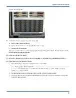
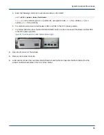
a. For blower cabinets, place the MAIN DISCONNECT switch on the rear panel of the blower cabinet PDU
in the ON (up) position.
b. For cabinets, place main circuit breakers CB1 and CB2 in the ON (up) position.
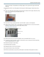
Figure 47. Circuit Breakers for Cabinet (left) and Blower (right)
a. Close the rear door of the cabinet.
b. Enter the following command in a terminal window on the SMW:
smw$
xtcli power up Hostname
Hostname
is the cabinet, system, or partition ID; examples include
c0-0
(for a cabinet),
S0
(for a
system), or
p0
(for a partition).
2.11 Cabinet Controller Backplane Replacement
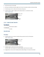
2.11.1 Remove a Cabinet Controller Backplane
Prerequisites
Tools Required:
T15 Torx driver
Small slotted screwdriver
Time Required:
30 minutes
About this task
The X and Y cabinet address information, cabinet type, and coordinated cooling region (CCR) position for the
cabinet controller is stored on the cabinet controller backplane SEEP. This information must be re-entered on the
operator interface when replacing the cabinet controller backplane.
Procedure
1. Power down all of the cabinets in the row.
System Cabinet Procedures
54