If the pump is inoperative for a long period of time, or
appears not to use any grease, remove and clean the cup
thoroughly. Caked grease in the cup can create a problem
of non-lubrication to the seal.
Under normal conditions, a grease cup full of grease will
last three to four months. If a grease seal requires grease
every day, and it is not leaking past the outer lip seal it
indicates that the seal is wearing out. The internal pressure
of the pump will often force the cup plunger out when the
seal leaks badly.
D-2) Shaft Seal Replacement:
All parts of the pump are easily dismantled by simply
removing nuts and screws. Rotating parts of the shaft seal
grip the shaft by friction and may be frozen to the shaft
through long usage.
If the mechanical shaft seal is not leaking and it is
necessary to dismantle part of the pump for inspection or
cleaning
DO NOT
disturb the shaft seal other than its
spring if the impeller is removed. Once a shaft seal has
been in operation it cannot be removed and replaced
without leaking.
CAUTION !
HANDLE PARTS WITH EXTREME CARE.
DO NOT SCRATCH OR MAR LAPPED SURFACES.
It is recommended to remove the pump side from the
support bracket. After the pump has been disassembled
make sure that the shaft and seat areas in the pump side
are as clean as possible. The shaft must not be sharp, but
neatly rounded and polished to a 1/32" radius. This radius
and the shaft, on which the rubber bellows grips, must be
polished with 180 to 240 grit emery cloth. The seal will
install relatively easy if the shaft is properly polished.
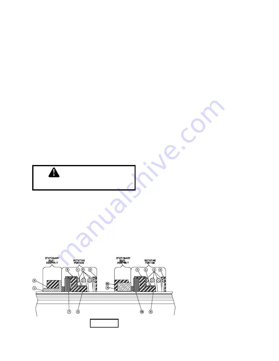
Install the seat assembly (1 and 2 or 1A and 2A, see Figure
2) in pump side adapter (12) using SAE# 10 oil on the
rubber parts. They may install easier by first inserting the
rubber part and then sliding the seat part into the rubber.
All of this must be done with the
fingers only
.
Now assemble the spring and rotating portion of the seal
onto the impeller shaft (19). Lubricate the impeller shaft
(19) and the inside of the bellows each with 2 or 3 drops
of SAE# 10 oil. Install this assembly into adapter (12), this
may take several minutes, therefore, oscillate the seal
back and forth on the shaft to make sure it does not stick
to the shaft until gage pin is in place and the clamp
tightened.
If for any reason the gage pin does not give proper
clearance, quickly adjust the impeller clearance before the
rubber bellows seats on the shaft.
D-3) Impeller:
These pumps have their impellers threaded on with right
hand threads.
The clearance between an open faced impeller and its
wear surface in the volute is set at the factory at
approximately .015 inches. This clearance is re-adjustable
by relocating the shaft at the clamping arrangement. In
cases where much sand is being pumped, close
clearances may bind the impeller and volute and overload
the motor. It may be necessary to provide extra clearance
on these.
When reassembling a dismantled pump, clean all parts
and especially areas where gaskets and o-rings are
located. Grease all gaskets and o-rings and areas where
o-rings must slide when assembling.
FIGURE 2
1 - Ni-Resist Stationary Seat
1A- Ceramic Stationary Seat
2 - Buna-N Seat Ring
2A- Buna-N Seat Cup
3 - Stainless Retainer
4 - Stainless Drive Band
5 - Stainless Spring
6 - Stainless Springholder
7 - Crane-Carb® Mating Ring
7A- Carbon Mating Ring
8 - Buna-N Bellows
Cross Section of Seals.
Two Styles Shown.
7
Содержание burks pumps WB12
Страница 8: ...FIGURE 3 8 ...
Страница 11: ... Crane Pumps Systems Inc 1994 2001 NOTES 11 ...


