background image

8

SECTION E: PREVENTATIVE MAINTENANCE

As the motor is oil filled, no lubrication or other maintenance 

is required, and generally CP&S pumps will give very reliable 

service and can be expected to operate for years on normal 

sewage pumping without failing. However as with any 

mechanical piece of equipment a preventive maintenance 

program is recommended and suggested to include the 

following checks:

WARNING ! - Pressure builds up due to heat.

1)  Inspect motor chamber for oil level and contamination and 


repair as required per section F-1.

2)  Inspect impeller and body for excessive build-up or clogging 


and repair as required per section F-2.

3)  Inspect motor and bearings and replace as required per


section F-3.

4)  Inspect seal for wear or leakage and repair as required per


section F-4.

SECTION F: SERVICE AND REPAIR

NOTE: All item numbers in ( ) refer to Figures 12, 13, 14 

& 15.

F-1) Lubrication:

Anytime the pump is removed from operation, the cooling oil 

in the motor housing (2) should be checked visually for oil 

level and contamination.

F-1.1) Checking Oil:

Motor Housing -

 To check oil, set unit upright. Remove pipe 

plug  (5)  from  motor  housing  (2).  With  a  flashlight,  visually 

inspect the oil in the motor housing (2) to make sure it is 

clean and clear, light amber in color and free from suspended 

particles. Milky white oil indicates the presence of water. Oil 

level should be just above the motor when pump is in a vertical 

position.

F-1.2) Testing Oil:

1.  Place pump on it’s side, remove pipe plug (5), from motor


housing (2) and drain oil into a clean, dry container.

2.  Check oil for contamination using an oil tester with a range


to 30 Kilovolts breakdown.

3.  If oil is found to be clean and uncontaminated (measure


above 15 KV. breakdown), refill the motor housing as per


section F-1.4.

4.  If oil is found to be dirty or contaminated (or measures


below 15 KV. breakdown), the the pump must be carefully


inspected for leaks at the shaft seal (46), cable assemblies


(52) and (53), square ring (42) and pipe plug (5)    


before refilling with oil. To locate the leak, perform


a pressure test as per section F-1.3. After leak is repaired,


refill with new oil as per section F-1.4.

F-1.3) Pressure Test:

Pumps that have had the oil drained from the Motor 

Housing -

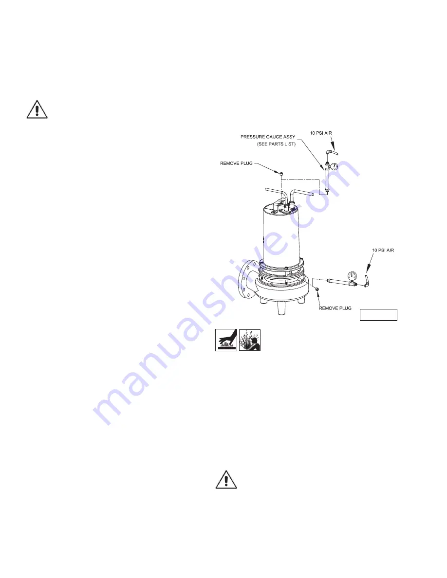
 Apply pipe sealant to pressure gauge assembly 

and tighten into pipe plug hole (See Figure 2).  Pressurize 

motor housing to 10 P.S.I. Use soap solution around the 

sealed areas and inspect joints for “air bubbles”. If, after 

five minutes, the pressure is still holding constant, and no 

“bubbles” are observed, slowly bleed the pressure and 

remove the gauge assembly. Replace oil as described in 

section F-1.4. If the pressure does not hold, then the leak 

must be located and repaired. 

Pumps that have NOT had the oil drained from the Motor 

Housing - 

The pressure test may be done with the oil at its 

normal level.  Remove pipe plug (5) from motor housing (2). 

Apply pipe sealant to pressure gauge assembly and tighten 

into hole (see Figure 2). Pressurize motor housing to 10 P.S.I. 

Use soap solution around the sealed areas above the oil level 

and inspect joints for “air bubbles”. For sealed areas below 

the oil level, leaks will seep oil.

If, after five minutes, the pressure is still holding constant, 

and no “bubbles”/oil seepage is observed, slowly bleed the 

pressure and remove the gauge assembly. If the pressure 

does not hold, then the leak must be located and repaired.

CAUTION ! - Pressure builds up extremely 

fast, increase pressure by “TAPPING” air 

nozzle. Too much pressure will damage 

seal. DO NOT exceed 10 P.S.I.

Seal Chamber -

 Set unit on its side with fill plug (5) 

downward, remove plug (5) and drain all oil from seal 

chamber. Apply pipe sealant to pressure gauge assembly 

and tighten into hole in bearing bracket (21). Pressurize seal 

chamber to 10 P.S.I. and check for leaks as outlined above.

F-1.4)  Replacing Oil:

Motor Housing-

 Set unit upright and refill with new cooling 

oil as per Table 1 (see parts list for amount). Fill to just above 

motor as an air space must remain in the top of the motor 

housing to compensate for oil expansion (see Figure 2, 12 or  

14). Apply pipe thread compound to threads of pipe plug (5) 

then assemble to motor housing (2).

IMPORTANT! - For single phase units, oil level 

should be below capacitor.

Seal Chamber -

 Set unit on its side, with plug (5) upward, 

and refill with new oil as per Table 1 (see parts list for 

amount). Apply pipe thread compound to threads of pipe plug 

(5) and assemble to bearing bracket (21).

FIGURE 2

Содержание 4SE2824DS

Страница 1: ...ems Inc constant product improvement program product changes may occur As such Crane Pumps Systems reserves the right to change product without prior written notification 420 Third Street 83 West Drive Brampton Piqua Ohio 45356 Ontario Canada L6T 2J6 Phone 937 778 8947 Phone 905 457 6223 Fax 937 773 7157 Fax 905 457 2650 www cranepumps com Form No 140838 Rev C Series 4SEV DS 2 8 3 7 5HP 1750RPM 60...

Страница 2: ...ENT PARTS 12 WIRE SCHEMATICS 13 TROUBLE SHOOTING 14 CROSS SECTION 1750RPM Fig 12 15 EXPLODED VIEW 1750RPM Fig 13 16 PARTS LIST 17 18 WARRANTY 19 RETURNED GOODS POLICY 20 WARRANTY REGISTRATION 20 Other brand and product names are trademarks or registered trademarks of their respective holders Barnes is a registered trademark of Crane Pumps Systems Inc 1991 2002 2003 1 06 8 06 2 07 Alteration Rights...

Страница 3: ...NOT insert fingers in pump with power connected Always wear eye protection when working on pumps Make sure lifting handles are securely fastened each time before lifting DO NOT operate pump without safety devices in place Always replace safety devices that have been removed during service or repair Secure the pump in its operating position so it can not tip over fall or slide DO NOT exceed manufac...

Страница 4: ...0 HR L10 Design MOTOR Design NEMA L Single phase NEMA B Three Phase Torque Curve Oil Filled Squirrel Cage Induction Winding Class B Class H Rated Magnet Wire Class F on selected models Service Factor 1 15 SINGLE PHASE Permanent Split Capacitor PSC Includes overload protection in motor THREE PHASE 200 230 460 60Hz is Tri voltage motor 575V Requires overload protection to be included in control pane...

Страница 5: ...lift station or basin The sump lift station or basin shall be vented in accordance with local plumbing codes This pump is designed to pump sewage effluent or other nonexplosive or noncorrosive wastewater and shall NOT be installed in locations classified as Class I Division 1 hazardous in accordance with the National Electrical Code NEC ANSI NFPA 70 or the Canadian Electrical Code Never install th...

Страница 6: ... for continuity resistance no moisture and the junction box control box for moisture content The above situations may induce a false signal in the moisture detecting circuit If none of the above test prove conclusive the pump s should be pulled and the source of the failure identified and repaired IF A MOISTURE DETECT HAS OCCURRED SCHEDULE MAINTENANCE AS SOON AS POSSIBLE If current through the tem...

Страница 7: ...A B 20 0 29 0 10 3 SOOW SOW 66 16 8 1 91 1 37 4SE3794DS 3 7 200 230 3 60 1750 B E B 16 1 14 0 35 9 42 7 12 4 SOOW SOW 68 17 4 7 64 1 77 4SE3744DS 3 7 460 3 60 1750 E B 7 0 21 3 14 4 SOOW SOW 57 14 5 7 08 4SE3754DS 3 7 575 3 60 1750 G B 5 6 21 6 14 4 SOOW SOW 57 14 5 11 39 4SE5024DS 5 0 230 1 60 1750 A F 28 0 59 0 10 3 SOOW SOW 66 16 8 0 60 2 20 4SE5094DS 5 0 200 230 3 60 1750 B D F 20 9 19 0 48 6 ...

Страница 8: ...l as per section F 1 4 F 1 3 Pressure Test Pumps that have had the oil drained from the Motor Housing Apply pipe sealant to pressure gauge assembly and tighten into pipe plug hole See Figure 2 Pressurize motor housing to 10 P S I Use soap solution around the sealed areas and inspect joints for air bubbles If after five minutes the pressure is still holding constant and no bubbles are observed slow...

Страница 9: ...oil from motor as outlined in paragraph F 1 2 Disassemble volute and impeller as outlined in paragraph F 2 1 and disassemble shaft seal as outlined in paragraph F 4 1 Position unit upright using blocks to avoid resting unit on shaft Unscrew cord hex bolts 6 and remove compression flange 52a and power cord 52 Remove snap ring 54 with a flat head screwdriver Pull the terminal block 56 out of the hou...

Страница 10: ...12 using connectors 11 and wire assemblies 12 as required Do not use wire nuts Slip motor leads and ground wire through fiberglass sleeve 10 Lower motor housing 2 down onto bearing bracket 21 while aligning holes and stringing motor leads through the cable entry bore s Slipping cords inside a 1 ft length of 5 conduit makes this easier Place socket head cap screws 51 into motor housing 2 and torque...

Страница 11: ...hange seal components replace the entire shaft seal 46 F 4 2 Reassembly Diaphragm At reassembly make sure the bulge and molded in part number of diaphragm 32 is facing the seal plate 25 With diaphragm 32 in place lay diaphragm clamp 43 in place on seal plate 25 and insert the four cap screws 44 and lock washers 9 and tighten Apply pipe thread compound to moisture sensor electrodes 18 if equipped o...

Страница 12: ...paragraph F 1 4 SECTION G REPLACEMENT PARTS G 1 ORDERING REPLACEMENT PARTS When ordering replacement parts ALWAYS furnish the follow ing information 1 Pump serial number and date code Paragraph G 4 2 Pump model number Paragraph G 3 3 Pump part number Paragraph G 2 4 Part description 5 Item part number 6 Quantity required 7 Shipping instructions 8 Billing Instructions G 2 PART NUMBER The part numbe...

Страница 13: ...13 FIGURE 11 ...

Страница 14: ...rity and condition Clean impeller and inlet of any obstruction 9 Loosen union slightly to allow trapped air to escape Verify that turn off level of switch is set so that the suction is always flooded Clean vent hole 10 Check rotation If power supply is three phase reverse any two of three power supply leads to ensure proper impeller rotation 11 Repair fixtures as required to eliminate leakage 12 C...

Страница 15: ...15 FIGURE 12 ...

Страница 16: ...16 FIGURE 13 ...

Страница 17: ...lt 5 16 18 x 1 00 Stainless 14 6 026322 Lock Washer 5 16 Stainless 15 2 2 31051 224 O Ring 16 2 105197 Retaining Ring 17 1 See Table Sensor Cable Assembly NOT Sold Separately 18 1 See Table Sensor Cable Terminal Block 19 2 038156 Machine Screw 6 32 x 3 8 LG Zinc Plated Steel 20 2 066843 Moisture Sensor 21 2 133404 Moisture Sensor Wire Assembly 16GA 20 0 LG 22 2 039934 Cap Plug 23 4 002204 Hex Head...

Страница 18: ...103769XL 103760 4SEV3794DS 109492XC 109492XF 109492XL 103586 4SEV3744DS 103742XC 103742XF 103742XL 103583 4SEV3754DS 103742XC 103742XF 103742XL 103583 4SEV5024DS 103769XC 103769XF 103769XL 103760 4SEV5094DS 103739XC 103739XF 103739XL 103586 4SEV5044DS 103742XC 103742XF 103742XL 103583 4SEV5054DS 103742XC 103742XF 103742XL 103583 MODEL NUMBER 30 FT SENSOR 50 FT SENSOR 100 FT SENSOR TERMINAL BLOCK S...

Страница 19: ... A RETURNED GOODS AUTHORIZATION CONTACT YOUR LOCAL CRANE PUMPS SYSTEMS INC DISTRIBUTOR Products Returned Must Be Cleaned Sanitized Or Decontaminated As Necessary Prior To Shipment To Insure That Employees Will Not Be Exposed To Health Hazards In Handling Said Material All Applicable Laws And Regulations Shall Apply IMPORTANT WARRANTY REGISTRATION Your product is covered by the enclosed Warranty If...

Отзывы: