background image

final page size: 8.5 x 5.5 in 

CRAFTSMAN

10 in. (254 mm) Folding Compound Miter Saw

Sierra de inglete compuesta plegadiza de 254 mm 

(10 pulgadas)

CMXEMAR120

INSTRUCTION MANUAL   |   MANUAL DE INSTRUCTIONES

IF YOU HAVE QUESTIONS OR COMMENTS, CONTACT US.

SI TIENE DUDAS O COMENTARIOS, CONTÁCTENOS.

1-888-398-7737      WWW.CRAFTSMAN.COM

Содержание CMXEMAR120

Страница 1: ... Miter Saw Sierra de inglete compuesta plegadiza de 254 mm 10 pulgadas CMXEMAR120 INSTRUCTIONMANUAL MANUALDEINSTRUCTIONES IFYOUHAVEQUESTIONSORCOMMENTS CONTACTUS SITIENEDUDASOCOMENTARIOS CONTÁCTENOS 1 888 398 7737 WWW CRAFTSMAN COM ...

Страница 2: ...English original instructions 1 Español traducido de las instrucciones originales 33 ...

Страница 3: ...ds This instruction manual uses the following safety alert symbols and words to alert you to hazardous situations and your risk of personal injury or property damage DANGER Indicates an imminently hazardous situation which if not avoided will result in death or serious injury WARNING Indicates a potentially hazardous situation which if not avoided could result in death or serious injury CAUTION In...

Страница 4: ... sense when operating a power tool Do not use a power tool while you are tired or under the influence of drugs alcohol or medication A moment of inattention while operating power tools may result in serious personal injury b Use personal protective equipment Always wear eye protection Protective equipment such as dust mask non skid safety shoes hard hat or hearing protection used for appropriate c...

Страница 5: ...ely to cause the saw blade to climb on top of the workpiece and violently throw the blade assembly towards the operator Never cross your hand over the intended line of cutting either in front or behind the saw blade Supporting the workpiece cross handed i e holding the workpiece to the right of the saw blade with your left hand or vice versa is very dangerous Do not reach behind the fence with eit...

Страница 6: ...r masonry products and arsenic and chromium from chemically treated lumber Your risk from these exposures varies depending on how often you do this type of work To reduce your exposure to these chemicals work in a well ventilated area and work with approved safety equipment such as those dust masks that are specially designed to filter out microscopic particles Handling the power cord on this prod...

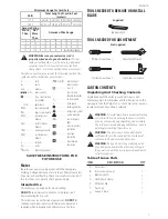
Страница 7: ... loss of power and overheating These tools are factory tested if this tool does not operate check power supply Intended Use This miter saw is designed for wood cutting DO NOT use under wet conditions or in presence of flammable liquids or gases This miter saw is a professional power tool DO NOT let children come into contact with the tool Supervision is required when inexperienced operators use th...

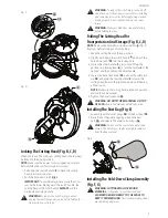
Страница 8: ...12 located behind the base as shown in Fig C 4 Pull out the safety lock pin 16 located next to the bevel lock knob 5 Grasp the cutting head by the switch handle 2 and raise the cutting head up to the vertical position just pass the 0 bevel setting 6 Tilt the cutting head back to 0 and then tighten the bevel lock knob 12 The pin will automatically insert into the slot locking the head in position 7...

Страница 9: ...OP OF SAW when in the folded or unfolded position Installing The Dust Bag Fig E 1 Squeeze the metal collar wings 18 of the dust bag 14 2 Place the dust bag neck opening around the dust port 19 and release the metal collar wings 18 WARNING Do not use this saw to cut and or sand metals The hot chips or sparks may ignite sawdust from the bag material Fig E Installing The Hold Down Clamp Assembly Fig ...

Страница 10: ...e Fig F 4 20 21 Fig G 20 20 Fig H 17 22 Mounting The Miter Saw Fig I J WARNING To avoid injury from unexpected saw movement Before moving the miter saw disconnect the power cord from the outlet and lock the cutting arm in the lower position using the hold down latch NOTE The hold down latch is for carrying or storing the tool It is not to be used for holding the saw while cutting Lower the cutting...

Страница 11: ...TE To avoid damage never carry the miter saw by the switch handle To reduce the risk of serious personal injury ALWAYS secure all clamps knobs latches and locks before lifting the saw 1 Never carry the saw by the switch handle miter clamp or cutting head The carrying handle 17 is appropriate for when the saw is folded only When saw is not folded the hand holds should be used 2 ALWAYS use the suppo...

Страница 12: ...ade 3 Place the blade wrench on the arbor bolt 27 4 Press the arbor lock button 28 holding it in firmly while turning the blade wrench counterclockwise Continue to press it in while tightening the arbor bolt securely Fig N 5 Rotate the cover plate 26 back to its original position and tighten the cover plate screw 25 with a Phillips screwdriver Fig M 6 Lower the blade guard 3 back to its original p...

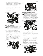
Страница 13: ... 2 5 mm hex wrench until the blade is square with the miter table 4 Tighten the bevel lock knob 12 after alignment is achieved Fig P 9 33 Fig Q 36 12 90 Bevel Pointer Adjustment Fig S WARNING To avoid injury from an accidental start make sure the switch is in the OFF position and the plug is not connected to the power source outlet 1 When the blade is exactly 90 0 to the table loosen the bevel poi...

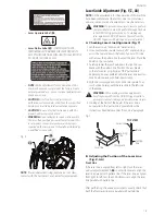
Страница 14: ...blade and the ruler against the fence 11 as shown 4 Adjust the fence 90 to the blade and tighten the four fence locking bolts 43 NOTE If the saw has not been used recently recheck blade squareness to the fence and readjust if needed 5 After fence has been aligned using a scrap piece of wood make a cut at 90 then check squareness on the piece Readjust if necessary Fig U 7 8 41 42 Turning Laser Guid...

Страница 15: ... Trigger Switch during any laser adjustment A Checking Laser Line Alignment Fig Y 1 Set the saw to a 0 miter and 0 bevel setting 2 Use a combination square to mark a 90 angle running across the top and down the front of a board This line will serve as the pattern line to adjust the laser Place the board on the saw table 3 Carefully lower the saw head down to align the saw blade with the pattern li...

Страница 16: ...p and blade changes Compare the direction of rotation arrow on the guard to the direction arrow on the blade The blade teeth should always point downward at the front of the saw Tighten the arbor bolt Tighten the cover plate screw Check for damaged parts Check for Alignment of moving parts Damaged electric cords Binding of moving parts Broken cracked castings base table motor upper arm Function of...

Страница 17: ...he elbow Noise levels vary widely To avoid possible hearing damage wear ear plugs when using any miter saw Always wear a face mask or dust mask along with safety goggles Inspect Your Workpiece Make sure there are no nails or foreign objects in the part of the workpiece being cut Plan your work to avoid small pieces that may bind or are too small to clamp and hold securely Plan the way you will gra...

Страница 18: ...age Always use the clamp to firmly hold the workpiece against the fence and table to prevent movement toward the blade Turn the laser guide on for pre alignment of your cut Fig BB With the power switch OFF bring the saw blade down to the workpiece to see the cutting path of the blade Raise the saw blade back up before turning the saw on Squeeze trigger switch to start saw Lower blade into workpiec...

Страница 19: ... 6 45 right left and 55 right IMPORTANT Always tighten the miter handle 7 before performing every cutting operation 5 Turn the laser guide on and position the workpiece on the table for pre alignment of your cut Fig DD 1 50 51 Bevel Cut Fig FF WARNING NEVER BEVEL to the right this saw is designed to only be used for cutting left bevel cuts 1 When a bevel cut is required loosen the bevel lock knob ...

Страница 20: ...ed 7 5 16 inches or more away from the blade The support must let the workpiece lay flat on the work table during the cutting operation NOTE When mounted on a flat surface the saw table is 3 1 2 inches high Support Base As Extension Table Fig JJ WARNING Before using make sure the height of the saw table matches the height of the support base 1 Place the miter saw and support base 10 on a flat stab...

Страница 21: ...ade application and thinness of the material Fig KK Blade slot Fig LL F e n c e Miter saw table Miter at 45 bevel at 0 Miter at 0 bevel at 45 F e n c e Miter saw table Workpiece Workpiece Cutting Crown Molding Fig MM NN Your compound miter saw is suited for the difficult task of cutting crown molding To fit properly crown molding must be compound mitered with extreme accuracy The two surfaces on a...

Страница 22: ...L 33 9 31 6 Right 1 Position top of molding against fence 2 LEFT side is finished piece Inside Corner Right Side IR 33 9 31 6 Left 1 Position bottom of molding against fence 2 LEFT side is finished piece Outside Corner Left Side OL 33 9 31 6 Left 1 Position bottom of molding against fence 2 RIGHT side is finished piece Outside Corner Right Side OR 33 9 31 6 Right 1 Position top of molding against ...

Страница 23: ... 23 84 22 01 117 20 67 24 31 23 43 21 68 118 20 30 23 94 23 02 21 36 119 19 93 23 57 22 61 21 03 120 19 57 23 20 22 21 20 70 121 19 20 22 83 21 80 20 38 122 18 84 22 46 21 40 20 05 123 18 48 22 09 21 00 19 72 52 38 Crown Molding 45 45 Crown Molding Angle Between Walls Miter Setting Bevel Setting Miter Setting Bevel Setting 124 18 13 21 71 20 61 19 39 125 17 77 21 34 20 21 19 06 126 17 42 20 96 19 ...

Страница 24: ... not use the saw without the lower blade guard The lower blade guard is attached to the saw for your protection Should the lower guard become damaged do not use the saw until the damaged guard has been replaced Regularly check to make sure the lower guard is working properly Also check before each use that all bolts screws are tight Clean the lower guard of any dust or buildup with a damp cloth WA...

Страница 25: ...25 English Free Warning Label Replacement If your warning labels become illegible or are missing call 1 888 398 7737 for a free replacement ...

Страница 26: ...outlet Brush spark when switch released 1 Brush worn 2 Other 1 Replace Brushes See MAINTENANCE section 2 Contact Service Center or Authorized Service Station SAW OPERATION PROBLEM CAUSE CORRECTION Blade hits table 1 Misalignment 1 Contact Service Center or Authorized Service Station Angle of cut not accurate Can not adjust miter 1 Miter table unlocked 2 Sawdust under table 1 See OPERATION Miter An...

Страница 27: ... 1 888 398 7737 This warranty does not apply to accessories or damage caused where repairs have been made or attempted by others THIS LIMITED WARRANTY IS GIVEN IN LIEU OF ALL OTHERS INCLUDING THE IMPLIED WARRANTY OF MERCHANTABILITY AND FITNESS FOR A PARTICULAR PURPOSE AND EXCLUDES ALL INCIDENTAL OR CONSEQUENTIAL DAMAGES Some states do not allow limitations on how long an implied warranty lasts or ...

Страница 28: ...AVE WASHER φ8 1 X7WV CR RE PAN HD TAPPING SCREW M4 16 2 X7Y7 FLAT WASHER φ6 φ13 1 1 X7WW CR RE PAN HD TAPPING SCREW M4 16 6 X7Y8 FLAT WASHER φ8 φ15 1 1 X7WX CR RE PAN HD TAPPING SCREW M3 8 1 X7Y9 ANCHOR BLOCK 1 X7WY CR RE TRUSS HD SCREW M5 20 2 X7YA COLLAR 1 X7WZ COMPRESSION SPRING 1 X7YB ANCHOR BLOCK 1 X7X0 CORD CLAMP 1 X7YC LOWER BLADE GUARD 1 X7X1 BUTTON SWITCH 1 X7YD SPECIAL BOLT 1 X7X2 TRIGGE...

Страница 29: ...X7ZK LASER WARNING LABEL 1 X80H ANCHOR PLATE 1 X7ZL LOCK NUT 1 X80J PLUNGER HANDLE 1 X7ZM NUT 1 X80K TENSION PLATE 1 X7ZN LOCK NUT 1 X80L SHAFT 1 X7ZP HEX NUT 1 X80M PIVOT SHAFT 1 X7ZQ CR RE PAN HD SCREW M5 8 1 X80N COMPRESSION SPRING 1 X7ZR CR RE PAN HD SCREW M5 8 2 X80P CLEVIS PIN 1 X7ZS CR RE PAN HD SCREW M5 8 1 X80Q HEX SOC HD CAP SCREW M8 30 4 X7ZT CR RE PAN HD SCREW M4 10 4 X80R HEX SOC HD C...

Страница 30: ...7WX X7XM X7WV2 X7X0 X7XR X7WU X7XX X7XW X7Y7 X7YG X80L X7X5 X7WP X7WY2 X7WQ X7X3 X7XN X80F X7ZY X807 X807 X7ZZ X7ZM X800 X803 X809 X801 X80C X7ZS X808 X804 X80P X80M X80G2 X80H X7Z7 X806 X805 X7XZ X7YA X7YJ X7YC X7YH X7YD X7YE X7ZC X7XT X7Y4 X7YB X7XV X7Y6 X7Y8 X7XU2 X7Y1 X7ZL X802 X7ZJ X7ZX X7ZP X837 X7WM X7YZ X80Q4 X80Y X80B X7ZV X7ZQ X80A X80W X7Z8 X7ZF X7ZW X80J X80N X80D X7ZN X7ZE X7ZR2 X80K ...

Страница 31: ...2 1 X81S GEAR BOX 1 X82S FLAT WASHER 1 4 3 4 1 16 2 X81T FLOW GUIDE 1 X82T FLAT WASHER φ5 φ16 2 1 X81U GEAR SHAFT 1 X82U BALL BEARING 1 X81V CUTTER SHAFT 1 X82V NEEDLE ROLLER 2 X82A ARMATURE ASS Y 1 X82W NEEDLE ROLLER BEARING 1 X82B HELIX GEAR 1 X82X BALL BEARING 1 X82C LEAD WIRE ASS Y 1 X82Y BALL BEARING 1 X82D HEX NUT M8 1 X82Z BALL BEARING 1 X82E CR RE PAN HD SCREW M5 6 5 X830 CLEVIS PIN 1 X82F...

Страница 32: ...English 32 NOTES ...

Отзывы: