background image

Содержание 944.627592

Страница 1: ...ety Rules and Instruct ons Before Operating This Equipment CRAFTSMAN 9 0 HP 21 INCH TINE WIDTH REAR TINE TILLER WITH COUNTER ROTATING TINES Assembly Operation Customer Responsibilities Service and Adjustments Repair Parts Sears Roebuck and Co Hoffman Estates IL 60179 U S A ...

Страница 2: ... tines shift into neutral and stop the engine Before Cleaning repairing or inspecting shut off the engine and make certain all movingpartshave stopped Disconnect the spark plug wire and keep the wire away from the plug to prevent accidental starting Disconnect the cordon electric motors Do not run the engine indoors exhaust fumes are dangerous Never operate the tiller without proper guards plates ...

Страница 3: ...THE ENGINE S EXHAUST SYSTEM IS EQUIPPED WITH A SPARK ARRESTER MEETING APPLICABLE LOCAL OR STATE LAWS IF ANY IF A SPARK ARRESTER IS USED IT SHOULD BE MAINTAINED IN EFFECTIVE WORKING ORDER BY THE OPERATOR IN THE STATE OF CALIFORNIA THE ABOVE IS REQUIRED BY LAW SECTION 4442 OF THE CALIFORNIA PUBLIC RESOURCES CODE OTHER STATES MAY HAVE SIMILAR LAWS FEDERAL LAWS APPLY ON FEDERAL LANDS SEE YOUR SEARS AU...

Страница 4: ...SAFETY RULES 2 CUSTOMER RESPONSIBILITIES 3 13 15 PRODUCT SPECIFICATIONS 3 WARRANTY 3 ASSEMBLY 5 7 OPERATION 8 12 MAINTENANCE SCHEDULE 13 SERVICE ADJUSTMENTS 15 18 STORAGE 19 TROUBLESHOOTING 20 REPAIR PARTS TILLER 21 31 4 ...

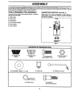
Страница 5: ...tandard wrench sizes are listed 1 Utility knife 1 Wire cutter 1 Screwdriver 1 Tire pressure gauge 1 Pair of pliers 1 9 16 wrench OPERATOR S POSITION See Fig 1 When right or left hand is mentioned in this manual it means when you are in the operating pesitior_ standing behind tiller handles FRONT LEFT RIGHT OPERATOR S POSITION FIG 1 W 1 Handle Lock Black CONTENTS OF HARDWARE PACK 1 Handle Lock Silv...

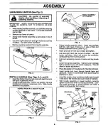
Страница 6: ...OSITION TIGHTEN HANDLE LOCK LEVER TO HOLD FIG 4 Rotate handle assembly down Insert rear carriage bolt first with head of bolt on L H side of tiller and loosely assemble Iocknut See Fig 5 Insert pivot bolt in front part of plate and tighten Cut down left hand rear corner of carton Lay roar carton wall down which will remove the protective cardboard flap from leveling shield Cut down remaining comer...

Страница 7: ... CHECK TIRE PRESSURE The tires on your unit were overinflated at the factory for shipping purposes Correct and equal tire pressure is important for best tillingperformance Reduce tire pressure to 20 PSI HANDLE HEIGHT Handle height may be adjusted to better suit operator See TO ADJUST HANDLE HEIGHT in the Service and Adjustments section of this manual FIG 6 CONNECT SHIFT ROD See Fig 7 Insert end of...

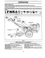
Страница 8: ...OL SHIFT LEVER INDICATOR RECOIL STARTER HANDLE CHOKECONTROL DEPTH STAKE LEVELING SHIELD OUTER SIDE SHIELD FIG 8 MEETS ANSI SAFETY REQUIREMENTS Our tillers conform to the safety standards of the American National Standards Institute DRIVE CONTROL BAR Used to engage tines DEPTH STAKE Controls depth at which tille will dig LEVELING SHIELD Levels tilled soil OUTER SIDE SHIELD Adjustable to protect sma...

Страница 9: ...hift lever indicator to F forward position Engage drive control bar and tiller will move forvvard REVERSE WHEELS ONLY TINES STOPPED DO NOT STAND DIRECTLY BEHIND TILLER Release the drive control bar Move throttle control to SLOW position Move shift lever indicator to R reverse position Hold drive control bar against the handle to start tiller movement DEPTH STAKE See Fig 10 The depth stake can be r...

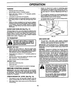
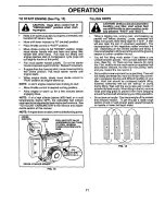
Страница 10: ...INE OIL LEVEL See Fig 12 The engine in your unit has been shipped from the factory already filled with SAE 30 summer weight oil With engine level clean area around oil filler plug and remove plug Engine oil should be to point of overflowing when engine is level For approximate capacity see PROD UCT SPECIFICATIONS on page 3 of this manual All oil must meet A P I Service Classification SF SG or SH F...

Страница 11: ...ERAL TURNSCOUNTERCLOCK WISE RECOIL STARTER HANDLE FIG 13 A AUTION Untilyouareaccustomedto handling your tiller start actual field use with throttle in slow position mid way between FAST and IDLE Tilling is digging into_turning over and breaking up packed soil before planting Loose unpacked soil helps root growth Best tillingdepth is 4 to 6 A tiller will also clear the soil of unwanted vegetation T...

Страница 12: ...he Service and Adjustments section of this manual If the tiller is unusually overloaded or jammed the shear pins are designed to break before internal damage occurs to the transmission If shear pin s break replace only with those shown in the Repair Parts section of this manual ADJUST WHEELS FOR CULTIVATING See Figs 16 and 17 Place blocks under right hand side of tiller and remove hairpin clip and...

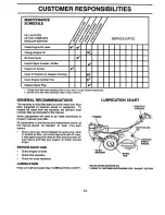
Страница 13: ...ue from the warranty the operator must maintain tiller as instructed in this manual Some adjustments will need to be made periodically to properly maintain your tiller All adjustments in the Service and Adjustments section of this manual should be checked at least once each season Once a year you should replace the spark plug clean or replace air filter and check tines and belts for wear A new spa...

Страница 14: ...er Remove drain plug For easier removal of plug use 7 16 12 pt socket with extension Tip tiller forward to drain oil After oil has drained completely replace oil drain plug and tighten securely Remove oil filler plug Be careful not to allow dirt to enter the engine Refill engine with oil See CHECK ENGINE OIL LEVEL in the Operation section of this manual OIL DRAIN PLUG_ OIL LEVEL PLUG AIR FILTER Se...

Страница 15: ...result ina shortened engine life SERVICE AND ADJUSTMENTS I A_ CAUTION Disconnect spark plug wire from spark plug and place wire where it cannot come into contact with plug TILLER TO ADJUST HANDLE HEIGHT See Fig 22 Select handle height best suited for your tilling conditions Handle height will be different when tiller digs into soil First loosen handle lock lever Handle can be positioned at differe...

Страница 16: ...by s ipping from engine pulley first Place new belt in groove of transmission pulley and into engine pulley BELT MUST BE IN GROOVE ON TOP OF IDLER PULLEY NOTE POSITION OF BELT TO GUIDES Tighten belt guides A and B Check belt adjustment as described below Replace belt guard Reposition wheel and replace clevis pin and hairpin clip GROUND DRIVE BELT ADJUSTMENT See Fig 25 For proper belt tension the e...

Страница 17: ...TINE WORN TINE To maintain the superb tilling performance of this machine the tines should be checked for sharpness wear and bending particularly the tines which are next to the transmission If the gap between the tines exceeds 3 1 2 inches they should be replaced or straightened as necessary New tines should be assembled as shown in Fig 28 Sharpened tine edges will rotate rearward from above TINE...

Страница 18: ... fuel temperature altitude or load If the carburetor does need adjustment proceed as follows IDLE RPM ADJUSTMENT TO adjust idle RPM rotate throttle linkage counter clockwise and hold against stop while adjusting idle speed adjusting screw to obtain 1750 RPM Re lease throttle linkage ACCELERATION TEST Move throttle control lever from SLOW to FAST position If engine hesitates or dies turn needle val...

Страница 19: ... STORAGE Drain the fuel tank Start the engine and let it run until the fuel lines and carburetor are empty Never use engine or carburetor cleaner products in the fuel tank or permanent damage may occur Use fresh fuel next season NOTE Fuel stabilizer is an acceptable alternative in minimizing the formation of fuel gum deposits during stor age Add stabilizer to gasoline in fuel tank or storage conta...

Страница 20: ...TART ENGINE inOperaUonsection 3 Waitseveralminutesbeforeattemptingto start 4 Clean or replaceair cleanercartridge 5 Drainfuel tankand carburetor and refilltankwithfresh gasoline 6 Removefuel tankand clean 7 Makesuresparkplugwire is seatedproperly on plug 8 Replacesparkplugor adjustgap 9 Makenecessaryadjustments 10 Replaceair filter 1 Place throttle control in FAST position 2 Clean or replace air c...

Страница 21: ...hift 109313X C _ommet Rubber 110702 Rod Shift 72140608 Bolt Carriage 3 8 16 x 1 109229X Lock Handle 73930600 Nut Centerlock 3 8 16 KEY PART NO NO DESCRIPTION 19 19131611 Washer 13 32xl xll Ga 20 109228X Lever Lock Handle 21 150628 Column Handle Asm 22 165197 Clip Plastic Cable 23 86777 Screw Hex Washer 10 24 x 1 2 24 9484R Clip 25 73970500 Locknut Hex Flange 26 138306 Clutch Cable 27 73220400 Nut ...

Страница 22: ...dicator Screw Hax Washer Head Slotted 10 24 x 1 2 Clip Washer Lock 1 4 Nut Hex 1 4 20 Screw Set Hex 5 16 18 x 3 8 Spacer Split 0 327 x 0 42 x 2 68 Washer 11 32 x 11 16 x 16 Gauge Sheave Transmission Nut Hex 5 16 18 Spacer Ring Retainer Key Square Spacer Split 523 x 718 x 2 Nut Cap 5 16 18 Tire Rim Tire Valve Rivet Drilled 26 33 23 24 25 KEY PART NO NO DESCRIPTION 25 4921H Clip Hairpin 26 102818X55...

Страница 23: ...umper Nut 5 16 18 Bolt Hex 5 16 18 x 1 3 4 Bracket Engine Bolt Hex Heed 3 8 16 x 1 Counter Weight R H Washer Lock 3 8 Nut Hex 3 8 16 Bolt Carriage 3 8 16 x 1 Clip Hairpin Rivet Drilled 13 5015J Tire 138417 Rim 795R Tife Valve 14 72470636 Bolt Carriage 3 8 16 x 4 1 2 15 74760672 Bolt Hex Head 3 8 16 x 4 1 2 16 7192J Tie Cable 17 Engine See Breakdown Briggs Model 19G402 1170 E1 NOTE All component di...

Страница 24: ...t Input Shaft Assembly Tine Spacer 1 008 x 1 3 4 x 645 Pinion Input Bearing Needle Gasket Gearcase KEY PART NO NO 26 106389X 27 100433M 28 8357J 29 674A289 30 6803J 31 12000040 32 8356J 33 100016K 34 106392X 35 106394X 36 100436L 37 142145 38 106393X 41 155236 42 10040700 43 73610700 44 162165 45 17720510 47 73220500 48 100107K 49 106391X 6066J DESCRIPTION Spacer 765 I D x 1 12 x 5 8 Gear Cluster ...

Страница 25: ...ake Shield Tine Bolt Carriage 5 16 18 x 3 4 Gr Nut Hex 5 16 18 Washer Lock 5 16 Washer Lock 1 4 Bracket Shield Tine Shield Side Outer R H KEY PART NO NO DESCRIPTION 16 73220400 Nut Fin Hex 1 4 20 17 104084X558 Shield Side 18 72040410 Bolt Carriage 1 4 20 x 1 1 4 Gr 5 19 102701X Grip 20 73220600 Nut Hex 3 8 16 21 138420 Stake Depth 22 74930632 Bolt Hex 3 8 16 x 2 23 4440J Hinge 24 72140408 Bolt Car...

Страница 26: ... Tine L H 14 2 100445L Hub Assembly 3 6557J Tine R H 14 4 101194M Tine LH 14 5 4929H Rivet Panhead 6 163552 Retainer Spring 7 10040600 Washer Lock 3 8 8 101193M Tine R H 14 9 74610616 Bolt Hex Head 3 8 24 x 1 10 73610600 Nut Hex 3 8 24 11 74610624 Bolt Hex Head 3 8 24 x 1 1 2 NOTE All component dimensions given in U S inches 1 inch 25 4 mm 26 ...

Страница 27: ... 9 165270 10 137282 11 157988 12 168260 13 162384 168560 168561 DESCRIPTION Decal Logo Decal Logo Decal Logo Decal Craftsman Decal Hand Placement Decal Shift Indicator Decal Warning Rotaing Tines Decal Caution Decal Briggs Stra_tton Decal Instr Decal Cou Rot Tines Decal Tine Depth Stake Decal Warning Till Eng Fr Manual Owner s English Manual Owner s French 27 ...

Страница 28: ... MODEL NUMBER 944 627592 ENGINE BRIGGS STRATI ON MODEL NUMBER 19G402 TYPE NO 1170 _E1 296 14 300 307_ 13 _ 12 3o8 13A 11036 LABEL KIT_ GASKET SET 7 8 10 it REQUIRES SPECIAL TOOLS TO INSTALL SEE REPAIRINSTRUCTION MANUAL 28 ...

Страница 29: ...REPAIR PARTS TILLER MODEL NUMBER 944 627592 ENGINE BRIGGS STRATTON MODEL NUMBER 19G402 TYPE NO 1170 E1 REQUIRES SPECIAL TOOLS TO INSTALL SEE REPAIR INSTRUCTION MANUAL 29 ...

Страница 30: ...e Intake Spring Valve Guard Flywheel Screw Sems Retainer valve Tappet Valve Gear Cam Elbow Intake _ Gasket Carburetor Mounting A Gasket Intake Manifold Stud Carb Mounting Housing Rewind Starter 56 295871 57 490179 58 88884 59 490653 60 490652 63 260414 64 281204 65 94904 66 399671 67 394897 68 63770 70 298799 71 394506 73 224874 74 94680 75 225136 75A 495659 93 281346 94 496589 95 94098 98 495800 ...

Страница 31: ...4642 Plug 304 491596 Housing Blower 956 493337 Fuel Tank Assembly 305 94786 Screw Sems 957 493988 Cap FueITank 306 496797 Shield Cylinder 958 399517 Valve Fuel Shut Off 307 94930 Screw Cylinder Shield 959 495664 Bracket Fuel Tank Upper 308 225055 Cover Cylinder Head 960 492990 Bracket Fuel Tank Lower 332 92284 Nut Flywheel 961 94095 Screw Tank Mounting 333 398811 Armature Magneto 965 94010 Nut Hex...

Страница 32: ...S ALWAYS GIVE THE FOLLOW tNG INFORMATION PRODUCT REAR TINE TILLER MODEL NUMBER 944 627592 ENGINE MODEL NUMBER 19G402 TYPE NUMBER 1170 E1 PART NUMBER PART DESCRIPTION Your Sears merchandise has added value when you consider Sears has service units nationwide staffed with Sears trained technicians profes sional technicians specifically trained to insure that we meet our pledge to you we service what...

Отзывы: