


8 — ENG
D20418 Rev. 0 2/22/00
Voltage and Circuit Protection
Refer to page 6 (Specification Chart) for the voltage and
circuit protection requirements of your compressor. Use
only a fuse or circuit breaker that is the same rating as
the branch circuit the air compressor is operated on. If
the compressor is connected to a circuit protected by
fuses, use only dual element time delay fuses.
If repairing or replacing cord or plug, the grounding wire
must be kept separate from the current-carrying wires.
Never connect the grounding wire to a flat blade plug
terminal. The grounding wire has insulation with an outer
surface that is green with or without yellow stripes.
If these grounding instructions are not completely under-
stood, or if in doubt as to whether the compressor is
properly grounded, have the installation checked by a
qualified electrician.
Location of the Air Compressor
Locate the air compressor in a clean, dry and well ven-
tilated area. The air filter must be kept clear of obstruc-
tions which could reduce air delivery of the air compres-
sor. The air compressor should be located at least 12"
away from the wall or other obstructions that will inter-
fere with the flow of fresh intake and cooling air.
Lubrication and Oil
This unit needs no lubrication or oiling.
Grounding Instructions
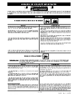
RISK OF ELECTRICAL SHOCK. In the
event of a short circuit, grounding reduces
the risk of shock by providing an escape
wire for the electric current. This air com-
pressor must be properly grounded.
This portable air compressor is equipped with a cord
having a grounding wire with an appropriate grounding
plug. The plug must be used with an outlet that has
been installed and grounded in accordance with all lo-
cal codes and ordinances. The outlet must have the
same configuration as the plug.
DO NOT USE AN
ADAPTER.
Inspect the plug and cord before each use. Do not use if
there are signs of damage.
IMPROPER GROUNDING CAN RESULT IN
ELECTRICAL SHOCK.
Do not modify the plug that has been
provided. If it does not fit the available
outlet, the correct outlet should be installed
by a qualified technician.
ASSEMBLY
1. Attach the handle to the compressor saddle by
inserting the handle
inside
the compressor saddle
and lining up the two bolt holes on each side. Install
the four screws, two on each side. Tighten securely.
2. Install one shoulder bolt and one nut for each wheel.
Tighten securely. The compressor will sit level if the
wheels are properly installed.
3. Clean and dry underside of air tank leg opposite
wheels. Remove the protective paper strip from the
adhesive backed rubber foot strip. Attach the
rubber foot strip to the bottom of leg. Press firmly
into place.
Installing Wheels, Handles, Rubber Foot
Strip
THE WHEELS AND HANDLE DO NOT
PROVIDE
ADEQUATE CLEARANCE,
STABILITY OR SUPPORT FOR PULLING
THE UNIT UP AND DOWN STAIRS OR
STEPS. THE UNIT MUST BE LIFTED, OR
PUSHED UP A RAMP.
BREAK-IN PROCEDURES
Содержание 919.727350
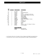
Страница 13: ...13 ENG D20418 Rev 0 2 22 00 REPAIR PARTS ...
Страница 14: ...14 ENG D20418 Rev 0 2 22 00 AIR COMPRESSOR DIAGRAM ...
Страница 16: ...16 ENG D20418 Rev 0 2 22 00 COMPRESSOR PUMP DIAGRAM ...
Страница 31: ...13 FR D20418 Rev 0 2 22 00 Dépannage Pièces ...
Страница 32: ...14 FR D20418 Rev 0 2 22 00 SCHÉMA APPAREIL ...
Страница 34: ...16 FR D20418 Rev 0 2 22 00 SCHÉMA BLOC COMPRESSEUR ...