background image

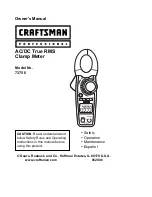
Owner's Manual 


AC/DC True RMS 
Clamp Meter 


Model No. 
73756


© Sears, Roebuck and Co., Hoffman Estates, IL 60179 U.S.A. 

www.craftsman.com                                      062006 

 Safety 

 Operation 

 Maintenance 

 Español 

CAUTION

: Read, understand and 

follow Safety Rules and Operating 
Instructions in this manual before 
using this product. 

Содержание 73756

Страница 1: ...Model No 73756 Sears Roebuck and Co Hoffman Estates IL 60179 U S A www craftsman com 062006 Safety Operation Maintenance Español CAUTION Read understand and follow Safety Rules and Operating Instructions in this manual before using this product ...

Страница 2: ...s 10 AC DC Current Measurements 10 DC Voltage Measurements 11 AC Voltage Measurements 12 Resistance Measurements 13 Capacitance Measurements 13 Frequency Measurements 14 Temperature Measurements 15 Continuity Check 15 Diode Test 16 Data Hold 17 DC Zero 17 Peak Hold 17 Display Backlight 18 Auto Power Off 18 Maintenance 19 Battery Replacement 20 Troubleshooting 21 Service and Parts 21 ...

Страница 3: ...harge This warranty gives you specific legal rights and you may also have other rights which vary from state to state Sears Roebuck and Co Dept 817WA Hoffman Estates IL 60179 For Customer Assistance Call 9am 5pm ET Monday through Friday 1 888 326 1006 WARNING USE EXTREME CAUTION IN THE USE OF THIS DEVICE Improper use of this device can result in injury or death Follow all safeguards suggested in t...

Страница 4: ...re 60V DC 24V AC 2 USE EXTREME CAUTION when working with high voltages 3 DO NOT measure voltage if the voltage on the COM input jack exceeds 600V above earth ground 4 DO NOT measure current of circuits whose voltage is greater than 500V above earth ground 5 NEVER connect the meter leads across a voltage source while the function switch is in the resistance or diode mode Doing so can damage the met...

Страница 5: ...oided may result damage to the product This symbol advises the user that the terminal s so marked must not be connected to a circuit point at which the voltage with respect to earth ground exceeds in this case 600 VAC or VDC This symbol adjacent to one or more terminals identifies them as being associated with ranges that may in normal use be subjected to particularly hazardous voltages For maximu...

Страница 6: ...ead SYMBOLS AND ANNUNCIATORS HOLD Data Hold Minus Sign Negative reading display 0 to 3999 Measurement display digits DC ZERO DCA Zero PMAX PMIN Peak capture AUTO Auto Range mode DC AC Direct Current Alternating Current BAT Low battery mV or V Milli volts or Volts Voltage Ohms Resistance A Amperes Current F Farad Capacitance Hz Hertz Frequency o F and o C Fahrenheit and Celsius units Temperature n ...

Страница 7: ...mV 0 1mV 1 0 10 digits 4 000V 1mV 40 00V 10mV 400 0V 0 1V 1 5 5 digits AC Voltage V AC 600V 1V 2 0 5 digits 400 0 0 1 1 0 4 digits 4 000k 1 40 00k 10 400 0k 0 1k 1 5 2 digits 4 000M 1k 2 5 3 digits Resistance 40 00M 10k 3 5 5 digits 4 000nF 1pF 5 0 30 digits 40 00nF 10pF 5 0 20 digits 400 0nF 0 1nF 4 000µF 1nF 40 00µF 10nF 3 0 5 digits 400 0µF 0 1µF 4 0 10 digits 4 000mF 1µF 10 10 digits Capacitan...

Страница 8: ...n 40 approx test current 0 5mA Temperature Sensor Requires type K thermocouple Input Impedance 10M VDC VAC AC Response True rms AAC and VAC ACV Bandwidth 50Hz to 400Hz Crest Factor 3 0 in 40A and 400A ranges 1 4 in 800A range 50 60Hz and 5 to 100 of range Overrange indication OL is displayed Auto Power Off 25 minutes approximately Polarity Automatic no indication for positive Minus sign for negati...

Страница 9: ...TION WARNING To avoid electric shock disconnect the test leads from any source of voltage before removing the battery cover 1 Disconnect the test leads from the meter 2 Remove the rear battery cover by removing the screw using a Phillips head screwdriver 3 Insert the battery into battery clips observing the correct polarity 4 Put the battery cover back in place and secure with the screw WARNING To...

Страница 10: ... is caused by the high input sensitivity The reading will stabilize and give a proper measurement when connected to a circuit AC DC Current Measurements WARNING Ensure that the test leads are disconnected from the meter before making current clamp measurements 1 Set the Function switch to the 800A 400A or 40A range If the approx range of the measurement is not known select the highest range then m...

Страница 11: ...hat can damage the meter 1 Insert the black test lead into the negative COM terminal and the red test lead into the positive V CAP TEMP Hz terminal 2 Set the function switch to the V Hz position 3 Use the MODE button to select DC Voltage 4 Connect the test leads in parallel to the circuit under test 5 The clamp meter LCD will display the reading V ...

Страница 12: ...g the metal contacts inside the outlet before assuming no voltage is present CAUTION Do not measure AC voltages if a motor on the circuit is being switched ON or OFF Large voltage surges may occur that can damage the meter 1 Insert the black test lead into the negative COM terminal and the red test lead into the positive V CAP TEMP Hz terminal 2 Set the function switch to the V Hz position 3 Use t...

Страница 13: ...RNING To avoid electric shock disconnect power to the unit under test and discharge all capacitors before taking any capacitance measurements Remove the batteries and unplug the line cords 1 Set the function switch to the CAP position 2 Insert the black test lead banana plug into the negative COM jack and the red test lead banana plug into the V CAP TEMP Hz positive jack 3 Touch the test probe tip...

Страница 14: ...the function switch to the V Hz Position 3 Press and hold the MODE button to select the Frequency Hz function k Hz will appear in the display 4 Touch the test probe tips across the part under test 5 Read the Frequency value on the display 6 The display will indicate the proper decimal point and value 7 Press and hold the MODE button again to return to the voltage mode Hz ...

Страница 15: ... to select o F or o C WARNING To avoid electric shock be sure the thermocouple probe has been removed before changing to another measurement function CONTINUITY CHECK WARNING To avoid electric shock never measure continuity on circuits or wires that have voltage on them 1 Insert the black test lead into the negative COM terminal and the red test lead into the V CAP TEMP Hz positive terminal 2 Set ...

Страница 16: ... LCD when in Diode test mode 3 Touch the test probe tips to the diode or semiconductor junction under test Note the meter reading 4 Reverse the test lead polarity by reversing the red and black leads Note this reading 5 The diode or junction can be evaluated as follows If one reading displays a value typically 0 400V to 0 900V and the other reading displays OL the diode is good If both readings di...

Страница 17: ... the peak AC or DC voltage or current The meter can capture negative or positive peaks as fast as 1 millisecond in duration 1 Turn the function switch to the A or V position 2 Use the MODE button to select AC or DC 3 Allow time for the display to stabilize 4 Press and Hold the PEAK button until CAL appears in the display This procedure will zero the range selected 5 Press the PEAK button Pmax will...

Страница 18: ...ight on Press again to turn the backlight off Note that the meter does have an auto power off feature as described below Automatic Power OFF In order to conserve battery life the meter will automatically turn off after approximately 25 minutes To turn the meter on again turn the function switch to the OFF position and then to the desired function position ...

Страница 19: ...RES Temperature extremes can shorten the life of the electronic parts and distort or melt plastic parts 3 HANDLE THE METER GENTLY AND CAREFULLY Dropping it can damage the electronic parts or the case 4 KEEP THE METER CLEAN Wipe the case occasionally with a damp cloth DO NOT use chemicals cleaning solvents or detergents 5 USE ONLY FRESH BATTERIES OF THE RECOMMENDED SIZE AND TYPE Remove old or weak ...

Страница 20: ...he left hand side of the LCD display The battery should be replaced 2 Follow instructions for installing batteries See the Battery Installation section of this manual 3 Dispose of the old battery properly WARNING To avoid electric shock do not operate your meter until the battery cover is in place and fastened securely NOTE If your meter does not work properly check battery to make sure that it is...

Страница 21: ...ck to be sure the battery is good If You Do Not Understand How the Meter Works 1 Purchase Multitesters and Their Use for Electrical Testing Item No 82303 2 Call our Customer Service Line 1 888 326 1006 SERVICE AND PARTS Item Number Description 93894 9V battery 82378 Set of black and red Test Leads 73756 D Replacement battery cover 73756 C Front Cover 73756 CS Rear cover screws 82377 Thermocouple p...

Отзывы: