background image

Содержание 580.328330

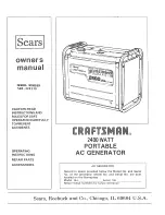
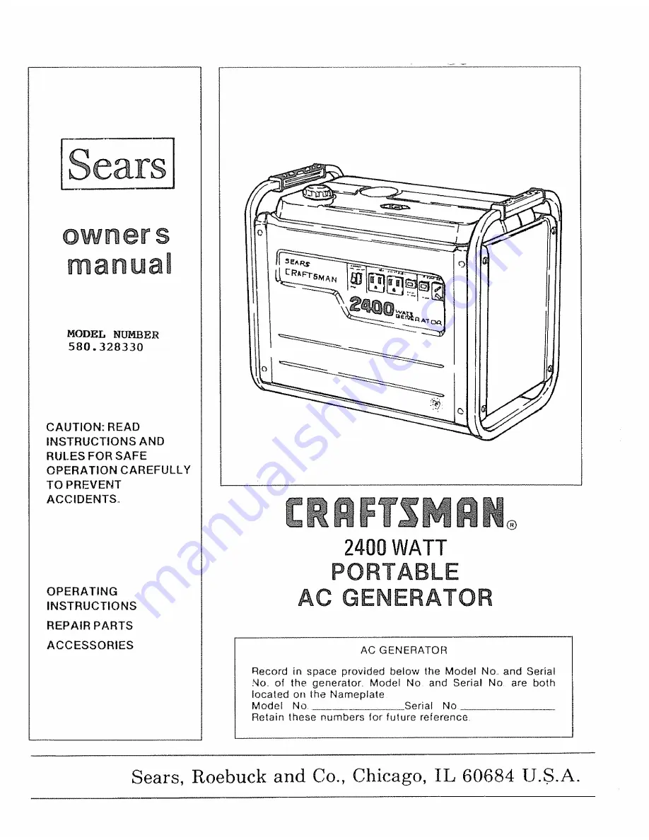
Страница 1: ...TING INSTRUCTIONS REPAIR PARTS ACCESSORIES 2400WATT PORTABLE AC GENERATOR AC GENERATOR Record in space provided below the Model No and Serial No of the generator Model No and Serial No are both located on the Nameplate Model No Serial No Retain these numbers for future reference Sears Roebuck and Co Chicago IL 60684 U S A ...

Страница 2: ... equipment only in well ventilated areas Never operate this equipment in any room or enclosed space where exhaust gases might accumulate and endanger people 4 This equipment requires an adequate free flow of cooling air for its operation Without adequate cooling air flow overheating and resultant damage to equipment and or property will result Never operate the generator inside any room or enclosu...

Страница 3: ...s 207 cc Compression Ratio 6 4 to 1 Cylinder Block Material High Silicon Aluminum Ignition System Type Flywheel Magneto with Breaker Points Recommended Spark Plug Resistor Type 14 mm _ NGK BMR 6A CHAMPION RCJ 8 Set Spark Plug Gap to 0 023 0 027 inch 0 6 0 7 mm Set Breaker Point Gap to 0 01 0 02 inch 0 3 0 5 mm Ignition Timing Fixed at 23 degrees BTDC Engine Speed Governor Type Mechanical Fixed Spe...

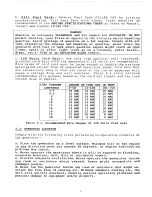
Страница 4: ... This slightly high engine speed setting at no load helps ensure that engine speed and a c frequency do not drop excessively when heavier electrical loads are applied Use of a multiple viscosity oil will contribute to easier starting in cold weather Use of UNLEADED gasoline in a 4 cycle engine contributes to in creased valve life by reducing lead and and carbon deposits A high quality REGULAR grad...

Страница 5: ...andling operating and servicing in structions that if not complied with fully may result in damage to equipment Under this heading will special emphasis NOTE be found explanatory statements 1 3 EQUIPMENT DESCRIPTION that require This equipment is a gasoline engine driven revolving field a c gener ator set The generator may be used to operate 120 volts single phase 60 hertz a c electrical devices r...

Страница 6: ...he generator from its shipping carton and from any shipping pallet to which it might be attached Remove all packing material from around the generator Inspect the unit carefully for any damage that might have occured during shipment In addition to this OWNERtS MANUAL a BATTERY CHARGE CABLE is shipped with the generator To order additional Manuals or Cables refer to the REPAIR PARTS section of the ...

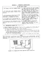
Страница 7: ...4 DON T touch areas around the engine exhaust muffler These areas are HOT 5 DON T handle electrical equipment while standing in water while barefoot or while hands or feet are wet 2 1 PI_PARATION BEFORE USE Figure 2 1 a Check Enqine Oii Level Figure 2 1 Check oil level and if necessary fill to proper level with the recommended oil as follows I Place the generator on a level surface 2 Remove OIL FI...

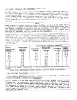
Страница 8: ...Table 2 1 lists minimum recommended wire gauges based on the cord set length and the load current draw in amperes COUNT AMPERES 2 3 4 5 6 8 i0 12 14 16 18 2O 0 50 18AWG 16 AWG 16 AWG 16 AWG 16 AWG 14 AWG 14 AWG 12 AWG 12 AWG I0 AWG 51 100 18 AWG 16 AWG 16 AWG 14 AWG 14 AWG 14 AWG 12 AWG 12 AWG 10 AWG 8 AWG LENGTH OF CORD SET IN FEET 101 150 18 AWG 16 AWG 14 AWG 12 AWG 12 AWG 12 AWG l0 AWG l0 AWG 8...

Страница 9: ... find the TYPE OF MOTOR and its RATED HORSEPOWER on the motor nameplate Then locate the approximate starting and running amperes in the chart MOTOR HORSEPOWER RATING 1 6 1 4 1 3 1 2 3 4 1 i 1 2 2 3 5 APPROXIMATE RUNNING A_PERES 2 3 3 3 3 8 5 0 7 1 8 3 12 3 16 7 25 0 40 0 APPROXIMATE STARTING AMPERES IREPULSION UNIVERSAL I INDUCTION CAPACITOR MOTORS I MOTORS _MOTORS 3 3 4 2 5_0 6 3 8 3 10 4 e 5 0 7...

Страница 10: ...VERLOAD THE GENERATOR SEE PARAGRAPH 2 3 A CLOSE THE CHOKE ENGINE RUN SWITCH B SET ENGINE SWITCH TO ON _ START Ft HANDLE C CRANK ENGINE Figure 2 2 Starting the Engine 2 5 STOPPING THE ENGINE a Disconnect or turn OFF all electrical loads connected to generator receptacles b Let the engine run for a minute or two at no load to cool c Set the Engine Run Stop Switch to STOP position wait for the engine...

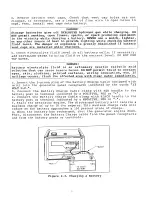
Страница 11: ...at can cause severe burns DO NOT permit fluid to contact eyes skin clothing painted surfaces wiring insulation etc If spillage occurs flush the affected area with clear water immediately c Insert the 2 prong plug of the Battery Charge Cable shipped with unit into the generator panel receptacle indicated by the words _12 VOLT D C d Connect the Battery Charge Cable clamp with RED handle to the batte...

Страница 12: ... GRAVITY PERCENT OF CHARGE 1 260 100 1 230 75 1 200 50 1 170 25 If necessary recharge the battery to a 100 STATE OF CHARGE EXAMPLE Readings obtained are 1 230 1 220 1 230 1 210 1 225 1 230 Sum of all readings is 7 345 Divide by 6 to obtain the average of 1 224 The battery is less than 75 charged Determininq Battery Condition If the difference in specific gravity _ etween the highest and lowest rea...

Страница 13: ...lished by a qualified engine service technician Prepare unit for storage if it is to remain idle longer than 30 days Table 3 1 Periodic Maintenance Chart 3 1 CHECK ENGINE OIL LEVEL Check engine crankcase oil level prior to each use or at least every 5 hours of operation See Paragraph 2 1 3 2 CHANGE ENGINE OIL Figure 3 1 Drain crankcase completely and refill with clean fresh oil after the first 20 ...

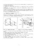
Страница 14: ... AIR CLEANER Figure 3 2 3 3 Service the engine air cleaner every 50 hours of operation more frequently if operating under extremely dirty or dusty conditions To service the air cleaner proceed as follows COVER Fire 3 2 Remove End Panel i Figure 3 3 Air Cleaner Assembly a Remove 4 screws that retain END PANEL to cradle then remove END PANEL b Unsnap the LATCH then remove COVER ELEMENT and PLATE c W...

Страница 15: ...t be maintained in effective working order by the operator In the State of California the preceding is required by law Section 4442 of the California Public Resources Code Other states may have similar laws Federal laws apply on federal lands a Remove 4 screws that retain rear PANEL to cradle then remove the rear PANEL b Remove SCREWS that retain SPARK ARRESTOR SCREEN and GASKET to exhaust muffler...

Страница 16: ...eration or if damaged or defective Use replacement spark plug as recommended in ENGINE SPECIFICATIONS CHART at front of Manual Set gap on new or used spark plug to 0 023 0 027 inch 0 6 0 7 mm a Remove COVER by prying upward b Use a spark plug socket wrench to remove spark plug c Set gap on spark plug as specified d Install spark plug with gasket Tighten plug by hand until it is firmly seated Then ...

Страница 17: ... out of gas b Let the engine cool c When engine has cooled remove spark plug see Paragraph 3 6 Then pour about 2 or 3 tablespoons of clean fresh engine oil into spark plug opening in engine cylinder head Crank engine several times to distribute oil d Install spark plug and spark plug access cover e Slowly pull starter handle out until resistance is felt indicating that engine is on its compression...

Страница 18: ... _ BRIDGE DIODE I POWER _A ooYL 1 IGN _o _ _ WI_ ING DfAG RAiv_ BRIDGE RECTIFIER T 3 tG _ a_ m i C _ 3 G_EEN TO TANK _ OUKt _IA fG F _ 0 ba ...

Страница 19: ...2400 WATT PORTABLE AC GENERATOR MODEL NUMBER 580 328330 I7 ...

Страница 20: ...2t 2O ASSEMBLE USING LOCKT TE 15 16 17 8 f J _ 3_r ITEMS SUPPLIED WITH ENGINE A EXPLODFn VIEW OF AC GENERATOR Dra_ing Nnmber 65798 A X u_ H o _N tm _ItJ ffl 0 _n O i w _u o ...

Страница 21: ...6mm I Req d HOSE Fuel 300mm long I Req d MOUNT Vibration Engine 2 Req d MOUNT Vibration Generator 2 Req d WASHER Flat MI0 i Req d GROMMET Lead Outlet i Req d HOUSING Engine Adapter i Req d CAPSCREW Hex Head M8 1 25 x 20mm 4 Req d FAN Cooling i Req d ROTOR ASSEMBLY Req d BEARING Ball i Req d RECTIFIER Battery Charge i Req d BOLT Rotor M8 25 x 190mm i Req d STATOR ASSEMBLY i Req d CARRIER Rear Beari...

Страница 22: ...41 26 4O 28 3 14 21 29 33 _H M 0 4 3 0 lm o i w ...

Страница 23: ...q d RETAINER 12 Volts d c Receptacle i Req d SCREW Machine M3 0 50 x 5mm 2 Req d SCREW Machine with Lock Washer M5 0 80 x 12mm 25 Req d COVER Handle 4 Req d TANK Fuel 2 34 U S Gallons i Req d CAP Fuel Tank i Req d BREATHER Fue Tank i Req d GASKET Fuel Tank Cap i Req d COVER Spark Plug Access i Req d INDICATOR Fuel Level I Req d CABLE Battery Charge i Req d DECAL Receptacle and Control Panel i Req ...

Страница 24: ...55 _ 57 _b s6 D 76 64 36 78 77 8O I 79 87 79 88 35 6O 65 82 8 99 44 59 53 74 i8 i7 2O 103 t05 5O 47 48 52 5i 22 21 46 49 I6 I10 t3 7 23 m x i m m o 1 t ...

Страница 25: ...PIPE Inlet 49 151 65t 88 GAS K E T 50 152 65188 GASK ET 51 153o65 88 NUT 16 ram 52 154 65188 WASH E R 53 155 65188 STUD 54 66391B GAUGE Fuel Level 55 66802A CAP Fuel Tank ENGINE ITEM 56 57 58 59 60 61 62 63 64 65 66 67 68 69 7O 71 72 73 74 75 76 77 78 79 80 81 82 83 84 85 86 87 88 89 90 91 92 93 94 95 96 97 98 99 100 101 102 t03 104 105 106 07 108 t09 110 t11 1t2 t13 PART NUMBER 66802C 668028 156 ...

Страница 26: ...8 65 88 DESCRIPTION CARBURETOR ASSEMBLY SHAFTChoke VALVEChoke SCREW JET Pilo 37 5 SCREW Pilol SPF_fNG SHAFT Throttte VALVE _hrott_e SCREW SCREW Stop ITEM 1I t2 13 14 15 16 I7 18 19 15 PART NUMBER 2t9 65188 220 65t88 221 65188 222 65188 223 65188 224 65188 225 65188 226 65188 227 65188 DESCRIPTION JET Main 77 5 NOZZLE Main 5A VALVE Needle FLOAT PIN Float GASKET CHAMBER Float BOLT GASKET 24 ...

Страница 27: ...RTER ASSEMBLY Recoil 228 65188 PULLEY 2 229 65188 BOLT 3 230 65188 RETAI N E R 4 231 65188 SPRING 5 232 65188 PAWL Recoil 6 233 65188 SP R I N G Return 7 234 65188 RE E L Recoil 8 235 65188 SPRING Recoil 9 236 65188 ROPE 4 5 x 550 0 237 65 88 HAND L E RecoilS tar ter 1 238 65 88 CASE Recoil Starter ...

Страница 28: ...he model number of you Alternator will be listed on the data plate WHEN ORDERING REPAIR PARTS ALWAYS GIVE THE FOLLOWING INFORMA TION o PART NUMBER o PART DESCRIPTION MODEL NUMBER NAME OF ITEM All parts listed may be ordered from any Sears Service Center and most Sears stores If the parts you need are not stocked locally your order will be electronically transmitted to a Sears Repair Distribution c...

Отзывы: