background image

Содержание 486.244120

Страница 1: ...6 244120 48 DOZER BLADE CAUTION Read Rules for Safe Operation and Instructions Carefully 48 DOZER BLADE Assembly Operation Customer Responsibilities Repair Parts Sears Roebuck and Co Hoffman Estates IL 60179 U S A PRINTED IN U S A ...

Страница 2: ...3 Never allow children to operate tractor and dozer blade and do not allow adults to operate withoutproper instructions 4 Always begin with transmission in first low gear and gradually increase speed as required 48 DOZER BLADE CARTON CONTENTS Also See Page 3 While confirming parts count we suggest that you clear any paint from the 1 8 pin holes in part reference numbers 2 3 and 4 to make assembly ...

Страница 3: ...t 3 8 16 x 1 1 4 U Rat Washer 3 8 Std V i_ I Pivot Bushing short W Hex Bolt 1 4 20 x 1 1 4 X Spacer long Y I rexLock Nut 1 4 20 Thread Z 11 Hex Bolt 1 4 20 x 5 8 A A Hex Bolt 3 8 16 x 1 AB Hex Jam Nut 5 16 24 Thread AC Clevis Pin 3 8 Dia x 3 4 Lg A _ Hairpin Cotter 5 32 AE i I Handle Guide AF Hex Bolt 1 2 13 x 4 Lg AE Hex Jam Nut 1 2 13 AFt 2 Rat Washer 7116 Std AI Lift Rod Trunnion AJ Hex Nut 3 8...

Страница 4: ...down through the top holes with a 3 8 lock washer and a 3 8 hex nut underneath Do not tighten at this time 3 8 X 1 1 4 CARRIAGE BOLT TOP HOLE _ 3 8 HEX NUT 3_ LOCK WASHER I ANGLE FRONT SLOT SPRING PIN HOLE CHANNEUPIVOT PLATE ASSEMBLY ANGLE LOCK SPRING FIGURE 3 3 Assemble the offset end of angle lock spring into small holes in angle lock bars as shown in figure 3 Slide lock bars through lock bar sl...

Страница 5: ...ee figures 7 and 8 1 4 X 1 1 4 HEX BOLT LONG SPACER ANGLE STOP CABLE END FITTING PUSH 1_ HEX LOCK NUT FIGURE 8 8 Assemble 1 4 x 1 1 4 hex bolt down through cable end fitting through long spacer angle stop right hand hole and through channel See figure 8 Secure with 1 4 hex lock nut and tighten the other 1 4 hex lock nut which was left loose in step 4 NOTE Keep cable and fitting in align ment with ...

Страница 6: ...e stop bolt must be located so that CENTER of bolt contacts the front axle The stop bolt must be tight_ ened in place before assembling blade assembly to channel FRONT AXLE FRAME lj8 CLEARANCE 1 2 X 4 HEX BOLT MINIMUM FIGURE 12 5 Hold blade head upright and guide one end of mount rod into hole near bottom of blade mount gusset See figures 11 and 13 Secure with a hairpin cotter Slide other end of m...

Страница 7: ...lift rod trunnion and lock nut removed from tractor lift link rod in tractor preparation section onto right and left hand lift link rods until one thread is below bottom of nut Tighten nuts lock trunnion in place See figure 16 FRONT LIFT LINK ROD RIGHT SIDE PLAIN HEX NUT NUT REMOVED EARLIER RGURE 16 LIFT LINK TRUNNION ONE _D EXPOSED 13 Pre assemble lift arm link to inside of long arm on lift assem...

Страница 8: ... 4 FRAME BRACKET REX J BOLTS_ J _ S AFTENO IFT ASSEMBLY_ _ LIFT PIVOT MOUNT PLATE ROD L H FIGURE 19 20 Assemble trunnions that were assembled re the lift link rods in step 12 through lift assembly arms and secure with 7 16 flat washers and small _ hairpin cotters Note Trunnions must be posi tioned to outside of lift assembly arms See figure 20 RIGHT HAND SIDE VIEW FRONT 7116 FLAT LIFT LINK ROD WAS...

Страница 9: ...plastic tie around handle tube and cable see figure 24 assembling end of tie through lock Pull plastic tie tight to retain cable to handle tube near front of tractor hood Cut oft extra plastic end 28 Assemble grip assembly to handle assembly us ing one 5 16 x 1 1 2 hex bolt and one 5 16 hex lock nut NOTE Do not over tighten lock nut grip assembly must pivot freely CABLE END f3_ HEX 5 16 x 1 1 2 FF...

Страница 10: ...n right hand side of tractor See figure 28 Move lever forward to lower d_ozerblade Pull lever back to raise dozer blade Pulling lever all the way back locks dozer blade in up position ATTACHMENT DEPTH CONTROL KNOB LEVER D Blade angle handle and grip assembly Located on right hand side of tractor See figure 28 NOTE Always raise dozer blade and Ioc_ in up position before moving angle control handle ...

Страница 11: ...shers and two 1 2 hex nuts I DO NOT OPERATE TRACTOR AND DOZER BLADE AT HIGH SPEEDS WITH SPRING TRIP ACTION IN LOCKED OUT POSITION FIGURE 31 _ NOTE Wheel weights and tire chains should be used with your dozer to improve traction For additional traction install wheel weight on rear of drawbar using a weight bracket kit and one wheel weight from the wheel weight kit These accessories are available st...

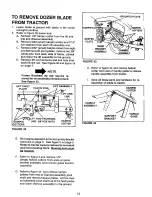
Страница 12: ... ROD TRUNNION HAIRPIN AND 318 HEX NUTS HAIRPIN COTTER COTTERS FIGURE 32 R H HITCHPLATE IAIRF KEEPER PLATE GUIDE BRACKET ASSEMBLY FIGURE 33 H Refer to figure 34 and remove hairpin cotter from end of handle guide to release handle assembly from tractor Save all loose parts and hardware for re assembly of blade to tractor HAIRPIN COTTER HANDLE ASSEMBLY FIGURE 34 HANDLE SUPPORT GUIDE BRACKET E F G Re ...

Страница 13: ...f Your Craftsman Tractor Seats offers a wide variety of attachments that for your tractor Many of these are listed below with brief explanations of how they can help you Most of these attachments do not require additional hitches or conversion kits those that do are indicated and are designed for easy attaching and detaching You may order these attachments at most Sears retail stores catalog sales...

Страница 14: ...REPAIR PARTS FOR MODEL 48 DOZER BLADE 64 56 26 56 64 52 3O 23 5 c 28 67 56 69 ...

Страница 15: ...PART NO 36 746 0260 37 43348 38 738 0234 39 44072 40 7071 41 43343 42 43064 43 41596 44 712 0206 45 43510 46 43353 47 710 0305 48 43003 49 43082 50 1509 90 51 43866 52 43013 53 23658 54 43085 55 44O44 56 43055 57 43087 58 43070 59 23625 60 43001 61 712 0256 62 731 0869 63 43019 64 43352 65 23923 66 23924 67 46001 68 43015 69 43407 45185 QTY 2 1 1 1 1 10 1 2 6 2 2 2 8 8 1 1 3 1 1 4 6 1 1 1 5 4 1 2 ...

Страница 16: ...and customer respon sibilities instructions in the owner s manual Sears will repair free of charge any defect in material or workmanship If this dozer blade is used for commercial or rental purposes this warranty applies for only 90 days from the date of purchase This warranty does not cover repairs necessary because of operator abuse or negligence including the failure to maintain the equipment a...

Отзывы: