

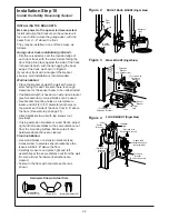
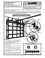


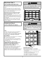


To open the door
manually: The door should
be fully closed if possible.
Pull down on the
emergency release handle
(so that the trolley release
arm snaps into a vertical
position) and lift the door
manually. The
lockout
feature prevents the trolley
from reconnecting auto-
matically, and the door can
be raised and lowered
manually as often as
necessary.
To re-engage the trolley:
Pull the emergency release
handle toward the opener at
a 45° degree angle so that
the trolley release arm is
horizontal. The trolley will
reconnect on the next UP or
DOWN operation, either
manually or by pressing the
Door Control command
button or the remote.
32
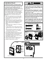
NOTICE
Emergency
Release Handle
(Pull Back
Towards Opener)
NOTICE
Emergency
Release Handle
(Pull Down)
Trolley
Release
arm
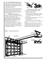
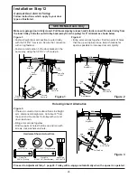
Weak or broken springs could allow an open
door to fall (either rapidly or unexpectedly),
resulting in serious injury, death or property
damage. If possible, use the emergency
release rope and handle
only when the door is
fully closed.
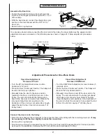
Press the lighted push button to open or close the
door.
Press again to
reverse the door during the closing
cycle or to
stop the door while it's opening.
Light Feature – Press the large round Light button. If
the opener lights are
off, they will turn on. If the
opener lights are
on, (even in the 4-1/2 minute
automatic cycle) they will turn
off.
But if you use the Light button to turn the lights
on
and then activate the opener, the lights will turn
off
after 4-1/2 minutes.
The Light button will not control the opener lights
when the door is in motion.
Lock Feature – The Lock feature is designed to
prevent operation of the door from remote controls.
However, the door will
open and close from the Door
Control, the Outdoor Key Switch and the Keyless
Entry Accessories.
To Activate: Press and hold the small round Lock
button for 2 seconds. The push button light will flash
as long as the Lock feature is
on.
To turn off: Press and hold the Lock button again for
2 seconds.The push button light will stop flashing.
The Lock feature will also turn off whenever the
“SRT” button on the opener panel is activated.
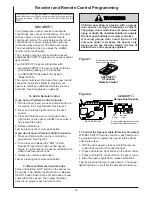
Operation of Your Opener
Operation of the Door Control
(See additional programming features, next page.)
WARNING
Activate the opener with any of the following:
• The Remote Control: Hold push button down until
the door starts to move.
• The Door Control: Hold push button down until the
door starts to move.
• The Outdoor Key Switch or Keyless Entry:
(See Accessories)
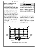
When the opener is activated with the safety
reversing sensor installed and correctly aligned:
1. If open, the door will close. If closed, it will open.
2. If closing, the door will reverse.
3. If opening, the door will stop (allowing space for
entry and exit of pets and for fresh air).
4. If the door has been stopped in a partially open
position, it will close.
5. If obstructed while closing, the door will reverse.
6. If obstructed while opening, the door will stop.
7. The garage door will reverse in the closing cycle,
and the opener lights will blink for 5 seconds, when
the invisible beam is broken. If fully open, the door
will not close when the beam is broken. The sensor
has no effect in the opening cycle.
If the sensor is not installed, or is not aligned correctly,
the door won't close from any remote transmitter. You
can close the door with the Door Control, the Outdoor
Key Switch, or Keyless Entry, however, if you activate
them
until down travel is complete. If you release them
too soon, the door will
reverse.
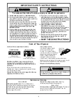
The Opener Lights will turn on under the following
conditions: When the opener is initially plugged in;
when the power is interrupted; when the opener is
activated. It will turn off automatically after 4-1/2
minutes or provide constant light when the Light
feature on the Premium Control Console is activated.
Bulb size is 75 watts maximum.
Lights will also turn on when someone walks through
the open garage door. With a
Premium Control
Console, this feature may be turned off as follows:
With the opener lights off, press and hold the light
button for 10 seconds, until the light goes on and off
again. To restore this feature, start with the opener
lights on, then press and hold the light button for 10
seconds.
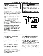
Manual Disconnect
Position
To Reconnect