User Manual
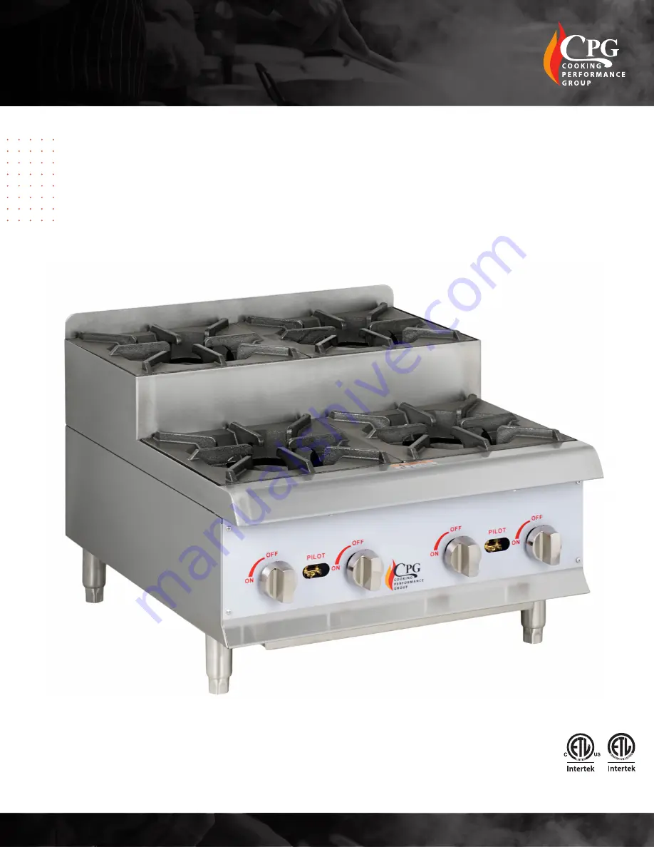
351SRCPG12NL | 351SRCPG24NL | 351SRCPG36NL
Cooking Performance Group
.
www.cookingperformancegroup.com
3182799
REVISED 04/2022
Countertop
Step-Up Ranges
Страница 1: ...User Manual 351SRCPG12NL 351SRCPG24NL 351SRCPG36NL Cooking Performance Group www cookingperformancegroup com 3182799 REVISED 04 2022 Countertop Step Up Ranges ...
Страница 2: ...uality of our products To ensure optimal performance we have outlined the following instructions and guidelines in this manual carefully for your review Cooking Performance Group declines any responsibility in the event users do not follow the instructions or guidelines stated here Note Dimensions do not include 3 depth for external regulator Specifications 351SRCPG12NL 351SRCPG24NL 351SRCPG36NL D...
Страница 3: ...ore or use gasoline or other flammable vapors and liquids in the vicinity of this or any other equipment Improper installation adjustment alteration service or maintenance could lead to property damage injury or death Read the installation operating and maintenance instructions thoroughly before installing or servicing CPG equipment This manual must be retained for future reference A fully license...
Страница 4: ... 1 Ensure gas supply and gas type as shown on unit nameplate match The nameplate is located on the side panel 2 Unit installation must conform with the National Fuel Gas Code ANSI Z223 1 NFPA 54 the National Gas Installation Code CSA B149 1 or the Propane Installation Code CSA B149 2 as applicable and in accordance with local codes 3 Use pipe threading compound or tape to seal all gas connections ...
Страница 5: ...te the unit at an elevation above 2 000 ft please see the below Gas Elevation Guide to find the proper orifice needed for installation 1 Remove the trivets from the top of the appliance 2 Remove the burner from the top of the gas pipe Fig 1 3 Replace the orifice fittings into the valve NOTE Unit number on the side of orifice fittings Fig 2 4 Install the front panel knobs 5 Before installing the re...
Страница 6: ...2NL 43 52 44 53 45 53 46 54 48 54 351SRCPG24NL 43 52 44 53 45 53 46 54 48 54 351SRCPG36NL 43 52 44 53 45 53 46 54 48 54 1 This unit must be installed under the proper hood regulations in accordance with local laws and guidelines 2 Do not obstruct the flow of combustion and ventilation air under the unit by the legs or behind the unit by the flue 3 This unit is not designed to be connected to an ev...
Страница 7: ...must be checked and lubricated periodically This must be done by an authorized service representative in your area Always ensure proper supervision while the equipment is in use Simple adjustments to knobs leg height etc do not require assistance from specialized personnel For more technical adjustments please consult a qualified technician Use only parts and accessories recommended by Cooking Per...
Страница 8: ...knobs to ON If the burner does not ignite promptly open the pilot valve more If the pilot flame appears larger than necessary turn it down and reset burner ignition The pilot flame should be as small as possible but large enough to guarantee reliable ignition of the burners when the knobs are turned to ON LIGHTING INSTRUCTIONS LIGHTING MAIN BURNER MAIN BURNER AIR SUPPLY LIGHTING PILOT NOTE For eff...
Страница 9: ...ner ports must be kept clean To clean burners boil them in a strong solution of lye water for 15 to 20 minutes Then either brush with a wire brush or clean gas ports with a sharp pointed metal instrument to ensure open ports DAILY CLEANING WEEKLY CLEANING NOTE Clean the regulator at least once a month Also make sure the vent opening is open and not blocked in any way Failure to do so will cause va...