

FCU320FULL
This manual is intended for Flight Simulator use only and may not be used in any
real world aviation application. The authors are not responsible for any errors or omissions.
FOREWORD
Thank you for purchasing CPflight FCU320 hardware. To optimize the performance of this unit,
please read through this manual carefully. This manual contains the latest information at the time of
drafting, eventual later information can be found at CPflight website www.cpflight.com
This manual gives you the information to connect and use the FCU320 with FSX, Prepar3D, Prosim
and/or add-on software. Even if the FCU320 supports the mainly used FS add-on software, it is not
possible to assure the full compatibility with all third part add-on. To know more about the
compatibility with a specific add-on aircraft please refer to the latest information on the CPflight
website, at the section “Technical and documents”.
Note: This manual contains the latest information at the time of drafting. Due to the continuous
evolving of the product some features could be been modified. Eventual later information can be
found at CPflight website www.cpflight.com
CPflight modules are produced to meet requirements from the hobby market; the use of our
products in professional or commercial environments is not permitted without approval of the
CPflight management; please contact us at info@cpflight.com if you need to exploit our products in
professional or commercial environments.
FCU320 is a full scale replica of the Airbus 320/340 Flight Control Unit, look and functionality are
reproduced with high details. FCU320 is equipped with high quality level components; custom made
LCD display and Push/pull knobs give high fidelity performances and a never seen kind of realism.
It is important to know that the hardware has not its own intelligence on board, it establishes an
interface with the software; logics, operating modes and aircraft behavior are managed by the
connected software.
HARDWARE INSTALLATION
WARNING! The panels back cover is made with stainless still metal sheet, pay particular
attention to the cutting edges while you are handling it.
Figure 1: FCU fixing
Fix the FCU through the 4 fixing nuts (see figure 1); connect the EFIS’s flat cables and place EFIS
in their location. EFIS are fixed through 3 nuts.
CONNECTIONS
The FCU320 can be directly powered by the USB
(starting from hardware revision 3.0);
the USB
port must have 500mA current capability (USB 2.0 or higher) or an HUB with its own power is
recommended. A standard 500mA USB can power the 2 EFIS (C F/O). If you
need to connect further CPflight expansion modules an optional power supply adapter is required.
Sockets for connections are on the back of panel (Figure 2). The two 20 pole sockets on sides
(Figure 2 E and F) are provided for EFIS connection; connect the flat cable of each EFIS to these
sockets.
WARNING! Do not invert the connection of right and left EFIS, the two EFIS have different
internal circuit and this could damage both the FCU and EFIS.
Using the FCU320 in a Project Magenta network system, connect the hardware to the computer
where the FCU software runs. Even if Project Magenta (and CPflight) FCU may run on a client,
mostly the data update result more fast if Project Magenta (and CPflight) FCU runs on the server.
Beyond to the EFIS connection and USB connectors the FCU320 has some further sockets: they
are provided to allow system expandability. A 16-pin connector “D” allows connection with side
panel available at our website, while DIN 5 pole socket “C” is used to link auxiliary CPflight
modules. Close to the left EFIS connection socket, there are two jumpers for firmware upgrade and
a small 2-pole socket ready for external backlight control.
Figure 2: Connectors (back view)
A -
Power supply socket (option)
B -
USB
C -
5 poles DIN socket for external module connection
D -
Side panel connectors
E -
Left EFIS connection
F -
Right EFIS connection
G -
External Backlight control
H -
Jumpers for firmware upgrade
USB DRIVER INSTALLATION
When you connect the FCU for the first time you will asked for driver installation, drivers are
downloadable at CPflight website. In relation with your OS the driver could be installed
automatically and already inside your PC. To install the drivers follows these steps:
Download the file “usb.zip” at our website www.cpflight.com
Files are in a compressed archive .zip; unzip the files in a temporarily folder…
Connect the USB cable to the FCU320 USB connector and the other side to a free USB
port of your computer. The computer has to be switched on when you connect the FCU for
the first time.
The driver installation procedure will start automatically; follow the instructions on the
screen (note that the figure of the following example may be different depending by your
operating system).
The drivers will be installed in the system
Important note: Depending by the system
may be required to repeat the driver
installation two times.
During the USB drivers installation the system assigns a number to the communication port. Check
your configuration in the Windows Control panel -> System Property -> Device Manager Tab. On
the (COM & LPT) port you will see “CPflight serial adapter (COM n)” where “n” is the assigned
communication port number, you will use this number in the First set up (see following).
COMMUNICATION SOFTWARE INSTALLATION
Besides the USB drivers a communication software is needed to use the FCU320 with the default
FSX Airbus.
Note: CPflight communication software allows to use the FCU320 with default FSX aircraft only. Do
not run the CPflight communication software using the FCU320 with third part software (Project
Magenta or other).
To install the communication software:
- Download instfsx_xxx.zip where xxx = revision number at
www.cpflight.com
- The file is in a compressed (zip) archive. Extract in a temporary folder and run the exe file to install
software (start PC as administrator to install software on Windows).
- CPflight communication software requires the popular FSUIPC library. If you do not have FSUIPC
in your system download it at
http://www.schiratti.com/dowson.html
.
FIRST SET UP AND START-UP
To start the hardware with default FSX select “Connect” in the FS Add-on menu -> CPflight -> FS-
COM. The first time you run FS-COM you will ask to select in the communication port number
(Setting COM); set the port number assigned during the USB driver installation.
Project Magenta:
To enable communication with Project Magenta you have to set the
communication port. In the Project Magenta FCU folder open “FCU.ini” file with a text editor, browse
the [Serial Connection] section and set CpflightComm= n where “n” is the communication port
assigned by the system during the USB drivers installation (check in your system which is your port
number). Save the “FCU.ini” file.
AST:
to enable the communication install the AST Interface software for CPFlight FCU/EFIS Unit;
download the file at Airsimtech website download page. To enable the communication set the
communication port number in the enclosed ini file. Open the ini file with a text editor, in the Serial
channel section set channel = n where “n” is the communication port assigned by the system during
the USB drivers installation.
Run Project Magenta FCU (or CPflightFCUinterface.com if used with AST) software to start-up the
FCU. The FCU320 will show on the displays the installed Firmware revision and the device serial
number and then synchronize data.
The FCU turns off command come from the computer when you close the software. If you shut-
down the computer without exit the program, or a computer block occur, the FCU may stay on or
may fail the subsequent turn on. If you find any problem with the FCU start or turn off, it is advisable
to reset the unit. To do this, disconnect the USB cable from the FCU, wait few seconds and
reconnect.
Important notes! The FCU can extinguish the displays to simulate a "cold and dark" situation
depending by the battery, avionics or other aircraft systems status. Be sure to have the
right conditions in the cockpit to have the display turned on - The 3 positions toggle
switches of EFIS selectors (ADF/OFF/VOR) have lock lever, pull the lever to move in the new
position.
Display bias angle
The bias angle is the angle from the perpendicular from which an LCD display is best viewed. The
bias angle is often stated with reference to a clock face. The better display viewing angle is from the
perpendicular to 60° bottom (see Figure 3). The horizontal viewing angle is 140°. These are the
better viewing condition for the expected placement in the cockpit.
A
C
B
H
D
F
E
G
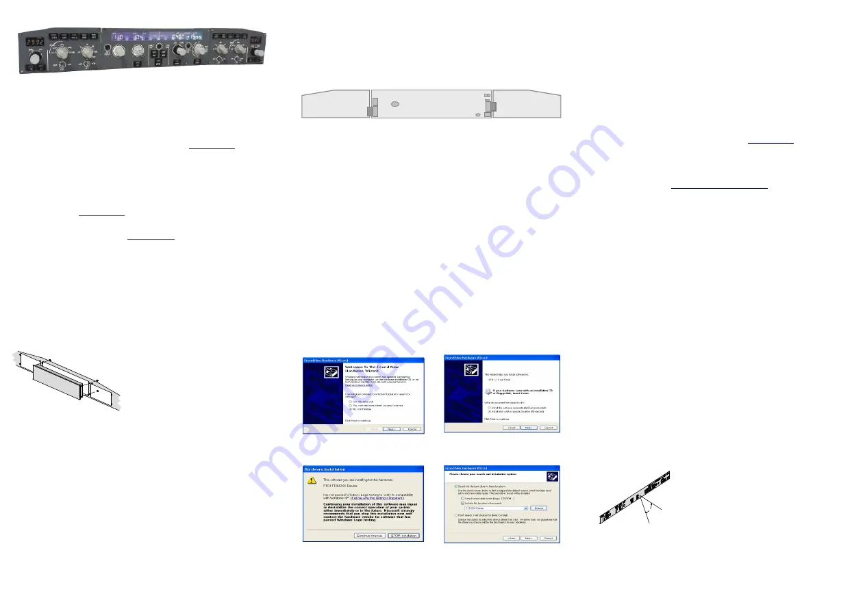
When you will ask to connect to Menus Update to
search for software select “No, not this time” and click
next to continue…
You will be informed that the driver has not
been subordinate to Menus Logo testing click
“Continue anyway.”
60,00
°
Figure 3:
display viewing angle
FCU320 is designed for panel assembly. The FCU320
is intended as a part to be inserted in a cockpit
reproduction, CPflight does not produce chassis or
other mechanical parts for the cockpit structure, so the
panel is intended to be inserted in your own cockpit
glare shield. The FCU is provided for “Captain only”
configuration (FCU + left EFIS), or in a full configuration
(FCU + LEFT efis Captain EFIS + F/O EFIS). In the
panel fixing cut-out consider the frontplates overhang to
keep enough space to place EFIS.
The FCU units has to be fixed before to place the
EFIS’s, differently you will not able to screw the fixing
nuts.
Select “Install from a list or specific location” and
click next to continue.
Browse the temporarily folder where you have
unzipped the files and click next to continue.