


page-
74
OASIS COVER
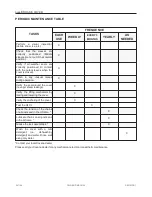
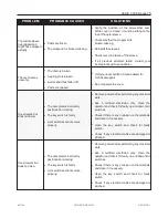
TROUBLESHOOTING
PROBLEM
PROBABLE CAUSES
SOLUTIONS
The cover does not
raise or lower (Silent
motor and no
movement)
l
The GFCI is tripped.
l
The power source is disconnected.
l
Reset the GFCI.
l
Verify that the power source is enabled.
l
Check the breaker panel.
l
Verify whether the cables were damaged or
pinched.
The cover does not
raise or lower. (Motor
humming and some
visible movement)
l
Posts are frozen.
l
Jack assemblies are jammed.
l
The motor is obstructed.
l
Posts are obstructed.
l
The debris on the cover is too
heavy.
l
Remove all the debris from the top of the cover.
l
Verify whether any posts are obstructed.
l
Use methanol to free ice buildup on posts.
l
Apply grease on the post assemblies.
l
Verify the relative position of the four posts
(See Foundation Preparation section).
l
Call your Local authorized Covana dealer.
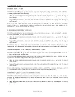
The posts are not
equally positioned.
l
The post screws (attached to the
outer shell) are loose.
l
The chain skipped during operation.
l
A spring pin at the bottom of a jack
is broken.
l
A drive shaft has fallen off.
l
Excessive weight on one side of the
cover.
l
Lower the cover completely and fasten the post
back in at the correct height.
l
Verify whether a drive shaft has fallen off and if
it is the case, reinstall the shaft.
l
Lower the cover and replace the chain.
l
Replace any missing or broken spring pin by
lifting the outer sleeve, using an awl and a
hammer..
l
Remove all debris from the top of the cover.
l
If all previous attempts failed, contact your
local authorized Covana dealer.
The shades are
loose, retract
improperly and/ or
disconnect from the
brackets. The
shades are wrinkling
or bulging at the
roller.
l
The internal spring is not wound
enough.
l
Too much tension in the internal
spring.
l
Holding bracket not parallels.
l
Consult shade installation manual.
l
Remove the bottom bar and reset the tension
back to “4 turns”.
l
Make sure the outer sleeves are sitting on the
foot plate, reposition the holding bracket so the
roller shade is moving straight.
241146
OWNER'S MANUAL
REVISION 1
Содержание OASIS COVER
Страница 1: ......
Страница 2: ......
Страница 54: ......
Страница 58: ...page 56 OASIS COVER WIRING DIAGRAM NORTH AMERICA 60 HZ 120 VAC OPERATOR 241146 OWNER S MANUAL REVISION 1...
Страница 59: ...OASIS COVER page 57 241146 OWNER S MANUAL REVISION 1...
Страница 60: ...page 58 OASIS COVER WIRING DIAGRAM NORTH AMERICA LIGHTS 60 HZ 120 VAC OPERATOR 241146 OWNER S MANUAL REVISION 1...
Страница 61: ...OASIS COVER page 59 241146 OWNER S MANUAL REVISION 1...
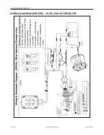
Страница 62: ...page 60 OASIS COVER WIRING DIAGRAM EUROPE 50 HZ 230 VAC OPERATOR 241146 OWNER S MANUAL REVISION 1...
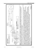
Страница 63: ...OASIS COVER page 61 241146 OWNER S MANUAL REVISION 1...
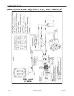
Страница 64: ...page 62 OASIS COVER WIRING DIAGRAM EUROPE LIGHTS 50 HZ 230 VAC OPERATOR 241146 OWNER S MANUAL REVISION 1...
Страница 65: ...OASIS COVER page 63 241146 OWNER S MANUAL REVISION 1...
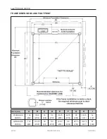
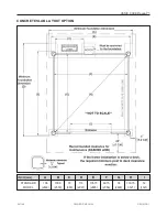
Страница 71: ...OASIS COVER page 69 TECHNICAL SPECIFICATIONS COVANA COVER FRONT VIEW 241146 OWNER S MANUAL REVISION 1...