Service Manual Ponygraphic
Chapter 3
Part Description
3.7
3.5.4. Assembly
Drawing
3.5.5. Warnings & Indications in Event of Failure.
•
Printing Failure
•
Paper jam during Printing
•
No Printout
3.6. Opto
Electronic
Assembly(C00095-01-05)
3.6.1. Function
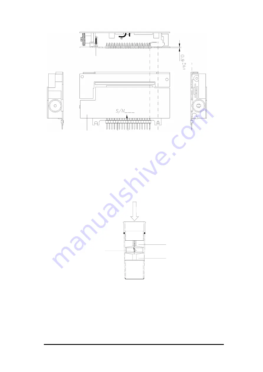
The flow meter is composed by a Bi-directional turbine and an Optoelectronic transducer.
The Turbine is made of (see figure) a transparent tube with two helical conveyors to which is
fixed (rotating free) a very lightweight rotor (blade).
Expired Flow
Conveyor
Conveyor
Rotor
(blade)
3.6.2. Description
The Optoelectronic transducer contains 2 couples of Infrared Emitter/Receiver diodes to detect
the position of the rotor. The air passing through the helical conveyors, takes a spiral motion
which causes the rotation of the turbine rotor. The rolling blade interrupts the infrared light
beamed by the diodes of the optoelectronic reader, each interruption represents half turn of the
rotor, this is used to measure the number of turn in the time. There is a constant ratio due to
software linearization between air passing through the turbine and number of turns. This allows
for an accurate measurement of volume and flows. Refeto the electrical diagram and layout of
the output signals from the infrared receivers D4 (Rx1) and D3 (Rx2) as shown following figure.


